Summary of HOW TO MULTIPLEX A 1-WIRE MASTER INTO NUMEROUS CHANNELS
This article explains using analog multiplexers with 1-Wire networks: adding per-channel pullups lets idle slaves remain powered and avoids wake-up delays, but you must account for the mux on-resistance (RON) when the master pulls the line low. Use small RON so VOL_MUX meets slave VIL. Maxim recommends the DS2477 for 3.3V systems (adjustable timing, triggers, internal pullups, high-impedance mode) and DS2484 for 5V. Separate overdrive-only and standard/overdrive slaves onto different mux channels. Select muxes with rail-to-rail support and low RON; use I2C muxes if MCU GPIO is limited.
Parts used in the How to Multiplex a 1-Wire Master into Numerous Channels:
- Analog multiplexer (recommended low RON, rail-to-rail)
- Post-mux pullup resistors (RP, e.g., RP4 and RP5)
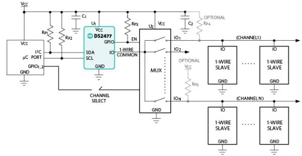
- Multiplexer with on-resistance RON (U2 in example)
- 1-Wire master DS2477 (recommended for 3.3V systems)
- 1-Wire master DS2484 (recommended for 5V systems)
- Microcontroller (µC) to control channel selection via GPIO
- MAX14661 or similar I2C-controlled mux (for limited GPIO MCU)
- 1-Wire slave devices (standard/overdrive and overdrive-only types)
Optionally, the mux (U2) has external, post-mux, pullup resistors (RP4 and RP5) to provide power for idle 1-Wire slaves when the switches are open. If this is not done, each time a channel switch is connected, the µC must wait the maximum wake-up time of the connected slaves on that channel (usually 2ms) before beginning communication.
However, it is important to consider the effects of the mux’s RON parameter during a pulldown event by the 1-Wire master when using an external pullup resistor on each channel. Any effects can be considered negligible by selecting a small RON to avoid violating the highest 1-Wire input low (VIL) parameter of the 1-Wire slaves. So, for a given post-mux pullup resistor of RP and a given mux resistor of RON, the post-mux output low voltage is expressed as follows:
VOL_MUX = VOL+ (VCC – VOL) × RON/(RON+RP)
Additionally, it is important to consider the flexibility of the 1-Wire master used. Maxim recommends the DS2477 1-Wire master for any 3.3V system because the DS2477 timing, input triggering levels, and internal pullup resistors are very adjustable. The DS2477 can also be set to a high impedance mode, which can be helpful when using the external resistor option. However, if a system needs 5V then the next best option is to use the DS2484.
Lastly, during this examination, some systems require a mix of overdrive only and standard/overdrive 1-Wire slave devices. If the overdrive only and the standard/overdrive devices reside on the same 1-Wire bus, communication faults occur. One simple solution is to use a mux that places overdrive only devices on different channels than the overdrive/standard devices. The DS2477 can then simple switch to overdrive mode or standard mode between the selection of channels for proper communication.
Analog Mux Selection
There are many requirements a designer considers when selecting the analog mux. These requirements can be the number of channels, interface type, cost, package type, and performance. Table 1 lists the Maxim recommended analog muxes for 1-Wire applications. All of the recommended analog muxes handle rail-to-rail analog signals, have a small RON, and come in various package types. The µC that controls the selected channel must have spare GPIO pins. If the µC does not have any spare GPIO pins, it is possible to use the MAX14661 or a similar device that can be tied to the same I2C bus used by the DS2477.
Read more: HOW TO MULTIPLEX A 1-WIRE MASTER INTO NUMEROUS CHANNELS
- Why add external post-mux pullup resistors to each channel?
To provide power for idle 1-Wire slaves when switches are open and avoid waiting the slaves maximum wake-up time before communication. - What effect does the mux on-resistance RON have when using external pullups?
RON raises the post-mux output low voltage; it must be small enough to avoid violating the 1-Wire slaves highest input low VIL. - How is the post-mux output low voltage calculated?
VOL_MUX = VOL + (VCC - VOL) × RON / (RON + RP) as given in the article. - Which 1-Wire master does Maxim recommend for 3.3V systems?
Maxim recommends the DS2477 for any 3.3V system. - Why is the DS2477 recommended?
Because its timing, input triggering levels, and internal pullup resistors are very adjustable and it can be set to a high impedance mode. - What should be done if a system requires 5V operation?
The article recommends using the DS2484 for 5V systems. - How can mixed overdrive-only and standard/overdrive slaves be handled?
Place overdrive-only devices on different mux channels than the standard/overdrive devices so the DS2477 can switch modes between channels to avoid communication faults. - What mux characteristics does the article recommend?
Use muxes that handle rail-to-rail analog signals and have a small RON; recommended Maxim analog muxes are listed in the article's table. - What if the microcontroller has no spare GPIO pins to control the mux?
Use the MAX14661 or a similar I2C-controlled device tied to the same I2C bus used by the DS2477.