Summary of How to make own serial LCD display for PIC12F683 Microcontroller
This article shows how to convert an HD44780 parallel alphanumeric LCD into a low-pin-count serial LCD for a PIC12F683 by using a 74HC595 shift register and a one-wire timed data-shifting protocol. It includes code snippets, LCD command definitions, timing/delay functions, and routines to send serial bits and 4-bit nibbles to the display so a single microcontroller pin can control the LCD.
Parts used in the Serial LCD project:
- HD44780 compatible alphanumeric LCD (e.g., 20x4)
- PIC12F683 microcontroller
- 74HC595 shift register
- Connecting wires
- Power supply (for MCU and LCD)
- Pull-up/pull-down resistors as needed
- Optional breadboard or PCB for mounting
Alphanumeric LCD generally HD44780 model is very popular display . This LCD use 8 pins for data display and three pin for control and AL together 16 pin . There will be problem on project if we have to connect numbers of components in single micro-controller to make a compact type of device . To reduce number of pin used in this tutorial we are going to make a serial LCD using data shifting technique.
In This project i am going to show you how to convert your parallel LCD display to serial LCD . Serial LCD is a little bit expensive but if we know this technique we can easily make cheap serial LCD by adding a 74HC595 chip .
code for this project is shown below
How to make own serial LCD display for PIC12F683 Microcontroller (Code)
#define _LCD_FIRST_ROW          0x80         //Move cursor to the 1st row

#define _LCD_SECOND_ROW         0xC0         //Move cursor to the 2nd row

#define _LCD_THIRD_ROW          0x94         //Move cursor to the 3rd row

#define _LCD_FOURTH_ROW         0xD4         //Move cursor to the 4th row

#define _LCD_CLEAR              0x01         //Clear display

#define _LCD_RETURN_HOME        0x02         //Return cursor to home position, returns a shifted display to

                                                 //its original position. Display data RAM is unaffected.

#define _LCD_CURSOR_OFF         0x0C         //Turn off cursor

#define _LCD_UNDERLINE_ON       0x0E         //Underline cursor on

#define _LCD_BLINK_CURSOR_ON    0x0F          //Blink cursor on

#define _LCD_MOVE_CURSOR_LEFT   0x10          //Move cursor left without changing display data RAM

#define _LCD_MOVE_CURSOR_RIGHT  0x14           //Move cursor right without changing display data RAM

#define _LCD_TURN_ON            0x0C         //Turn Lcd display on

#define _LCD_TURN_OFF           0x08         //Turn Lcd display off

#define _LCD_SHIFT_LEFT         0x18         //Shift display left without changing display data RAM

#define _LCD_SHIFT_RIGHT        0x1E         //Shift display right without changing display data RAM

sbit One_Wire at GP0_bit;

sbit One_Wire_Direction at TRISIO0_bit;

char msg1[] = "www.electronify.org";

char msg2[] = "4 bit One-Wire LCD";

char msg3[] = "20x4 LCD display";

char msg4[] = "HD44780 model";

void Delay_6ms() {

    Delay_ms(6);

}

void Delay_15us() {

    Delay_us(10);

}

void Send_Byte(char rs, char out_char) {

    char i = 0, mask = 0x80;

    out_char.F1 = rs;

    for(i = 0; i < 7; i++) {    // send all 7 bits
        if(out_char & mask) {   // if HI bit, make 1uS low pulse
             One_Wire = 0;      // make LO pulse
             One_Wire = 1;      // end LO pulse
             Delay_15uS();      // safe 15uS pulse recovery
        }
        else {                  // else is LO bit!
             One_Wire = 0;
             Delay_15uS();      // 15uS LO pulse
             One_Wire = 1;
             Delay_15uS();      // 30uS recovery
             Delay_15uS();
        }
        // now we have sent that bit out using Shift1 timed protocol!
        mask >>= 1;             // get the next bit

    }

    // The Shift1 protocol requires that the 8th bit is very

    // long, this causes the 74HC595 shift register to latch

    // all the 8 bits to its output port.

    // NOTE! the 8th bit (bit0) will always be received as zero.

    One_Wire = 0;        // send 8th bit, lo pulse = 14x15 = 210uS

    //for(i = 10; i; i--)Delay_15uS();

    Delay_us(210);

    One_Wire = 1;        // and hi recovery 20x15 = 300 uS

    //for(i = 14; i; i--)Delay_15uS();

    Delay_us(300);

}

void Write_Nibbles(char rs, char out_char) {

    char data2Send;

    data2Send = out_char & 0xF0;

    data2Send.F3 = 1;

    Send_Byte(rs,data2Send);

    data2Send.F3 = 0;

    Send_Byte(rs,data2Send);

    data2Send = out_char & 0x0F;

    data2Send <<= 4;
    data2Send.F3 = 1;
    Send_Byte(rs,data2Send);
    data2Send.F3 = 0;
    Send_Byte(rs,data2Send);
}
void Write_Nibble(char out_char) {
    char data2Send, rs = 0;
    data2Send = out_char & 0xF0;
    data2Send.F3 = 1;
    Send_Byte(rs,data2Send);
    data2Send.F3 = 0;
    Send_Byte(rs,data2Send);
}
void One_Wire_LCD_Cmd(char out_char) {
    char rs = 0;
    Write_Nibbles(rs,out_char);
    Delay_ms(5);
}
void One_Wire_LCD_Chr(char row, char col, char out_char) {
    char rs = 1;
    switch(row){
            case 1:
                One_Wire_LCD_Cmd(0x80 + col-1);
                break;
            case 2:
                One_Wire_LCD_Cmd(0xC0 + col-1);
                break;
            case 3:
                One_Wire_LCD_Cmd(0x94 + col-1);
                break;
            case 4:
                One_Wire_LCD_Cmd(0xD4 + col-1);
                break;
    }
    Write_Nibbles(rs,out_char);
}
void One_Wire_LCD_Chr_Cp(char out_char) {
    char rs = 1;
    Write_Nibbles(rs,out_char);
}
void One_Wire_LCD_Out(char row, char col, char *text) {
    while(*text)
        One_Wire_LCD_Chr(row,col++,*text++);
}
void One_Wire_LCD_Out_Cp(char *text) {
    while(*text)
        One_Wire_LCD_Chr_Cp(*text++);
}
void One_Wire_LCD_Init() {
    Delay_ms(150);
    Write_Nibble(0x30);
    Delay_ms(30);
    Write_Nibble(0x30);
    Delay_ms(30);
    Write_Nibble(0x30);
    Delay_ms(30);
    Write_Nibble(0x20);
    Delay_ms(20);
    One_Wire_LCD_Cmd(0x28);
    Delay_ms(10);
    One_Wire_LCD_Cmd(0x06);
    Delay_ms(10);
}
void main() {
     ANSEL = 0x00;
     TRISIO = 0x00;
     GPIO = 0x00;
     One_Wire = 1;
     One_Wire_LCD_Init();
     One_Wire_LCD_Cmd(_LCD_CLEAR);
     One_Wire_LCD_Cmd(_LCD_CURSOR_OFF);
     One_Wire_LCD_Out(1,1,"One-Wire");
     One_Wire_LCD_Out(2,1,"Serial LCD");
     One_Wire_LCD_Out(3,1,"20x4");
     One_Wire_LCD_Out(4,1,"Using 74HC595");
while(1){

     }
}
How to make own serial LCD display for PIC12F683 Microcontroller (Schematic Diagram)
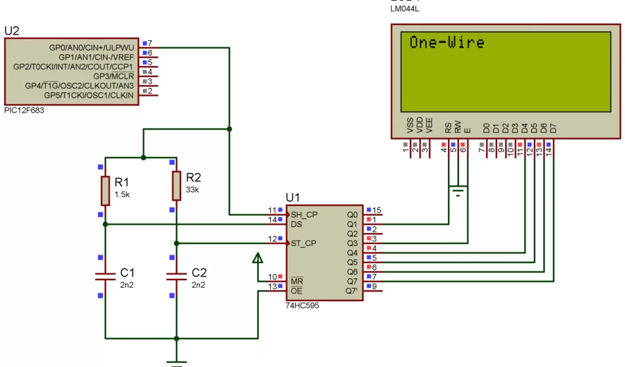
How this works ?
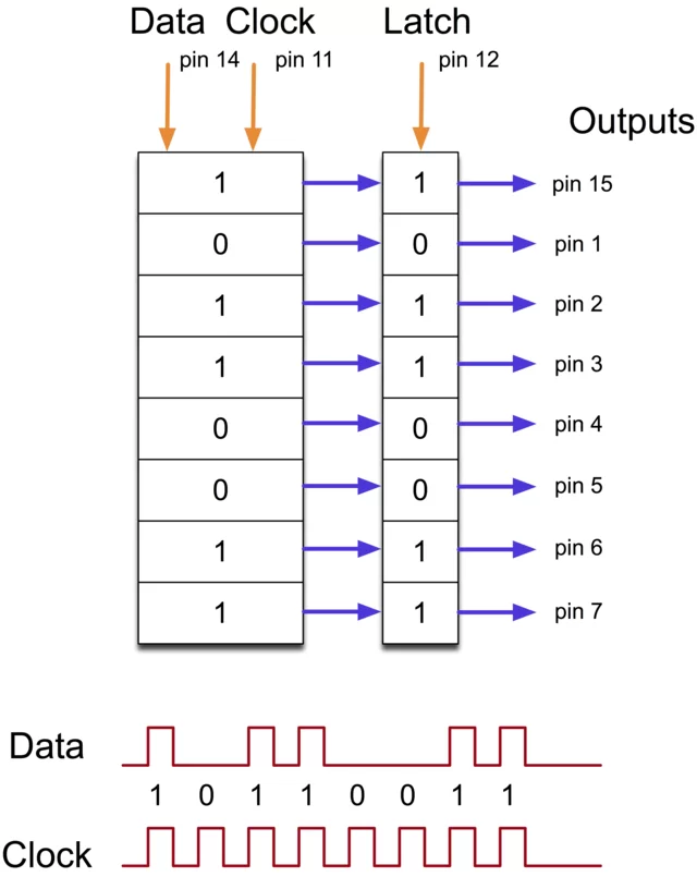
74hc595 is a kind of shift register . This chip converts serial data to parallel data (in this project we are connecting LCD on 4 bit mode this mode also shift remaining 4 bit data to higher register bit inside the LCD ) , so we are not doing anything new , we are just converting serial data into parallel so that we can reduce number of pin used on micro-controller .The shift register holds what can be thought of as eight memory locations, each of which can be a 1 or a 0.
To set each of these values on or off, we feed in the data using the ‘Data’ and ‘Clock’ pins of the chip. The clock pin needs to receive eight pulses, at the time of each pulse, if the data pin is high, then a 1 gets pushed into the shift register, otherwise a 0. When all eight pulses have been received, then enabling the ‘Latch’ pin copies those eight values to the latch register. This is necessary, otherwise the wrong LEDs would flicker as the data was being loaded into the shift register.
- What is the goal of this project?
The goal is to convert a parallel HD44780 LCD into a serial LCD using a 74HC595 and a one-wire data shifting technique to reduce microcontroller pin usage. - Which microcontroller is used in the example code?
The example uses the PIC12F683 microcontroller. - Which shift register is used to make the serial LCD?
The project uses the 74HC595 shift register. - How many microcontroller pins are required after conversion?
The article demonstrates using a single one-wire connection (one microcontroller pin) to control the LCD via the shift register. - What LCD model family is targeted?
The HD44780 compatible alphanumeric LCD family is targeted (example: 20x4 LCD). - What protocol or technique is used to send data serially?
A timed one-wire Shift1-like protocol is used, sending seven data bits followed by a long eighth bit to latch the 74HC595. - What timing functions are included in the code?
The code provides Delay_6ms and Delay_15us (Delay_ms and Delay_us calls) and specific microsecond delays for bit pulses and latching (e.g., 210us and 300us). - How are 8-bit LCD commands sent in 4-bit mode?
The code splits bytes into high and low nibbles and sends each nibble via Write_Nibbles which sets appropriate bits and calls Send_Byte.