Summary of How to interface Seven Segment Display with PIC18F4550 Microcontroller
Summary: This article explains interfacing a single seven-segment LED display (common anode or common cathode) with a PIC18F4550 microcontroller. It describes wiring, required data bytes to show digits 0–9, using mikroC IDE tools to generate segment codes, and provides example C code that cycles digits with delays. Typical applications and a circuit diagram and video are referenced.
Parts used in the Seven Segment with PIC18F4550:
- PIC18F4550 microcontroller
- Seven segment display (Common Anode or Common Cathode)
The seven segments are used to display decimal and hexadecimal (0-9, A-F) values. A seven segment is cheapest option for applications requiring numeric value display as output. Calculators, watches, lift’s floor indication panel etc. are examples of such applications. The interfacing and operation of a seven-segment display with PIC18F4550 has been explained here.
A typical seven-segment consists of 8 LEDs arranged in a pattern to display values. A seven-segment can be either of the two types, namely, Common Anode (CA) and Common Cathode (CC). For more details, refer Seven segments.
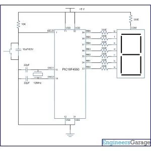
A single seven-segment requires a minimum of 7 data pins of controller to display different values. The connections of seven-segment with PIC18F4550 are shown in the adjoining circuit.
To display a numeric value, a particular data-byte is sent by the microcontroller. Refer seven segment interfacing with 8051. This data byte can either be calculated manually or by using Seven Segment Editor tool of mikroC IDE. (Also see Working with mikroC)
Project Source Code
###
// Program to Interface seven segment display with PIC18F4550 Microcontroller
// Configuration bits
/* _CPUDIV_OSC1_PLL2_1L, // Divide clock by 2
_FOSC_HS_1H, // Select High Speed (HS) oscillator
_WDT_OFF_2H, // Watchdog Timer off
MCLRE_ON_3H // Master Clear on
*/
#define seg_port LATB
void main(void)
{
TRISB=0; // Configure PortB as output port
while(1)
{
seg_port=0xC0; // Display ‘0’
Delay_ms(1000);
seg_port=0xF9; // Display ‘1’
Delay_ms(1000);
seg_port=0xA4; // Display ‘2’
Delay_ms(1000);
seg_port=0xB0; // Display ‘3’
Delay_ms(1000);
seg_port=0x99; // Display ‘4’
Delay_ms(1000);
seg_port=0x92; // Display ‘5’
Delay_ms(1000);
seg_port=0x82; // Display ‘6’
Delay_ms(1000);
seg_port=0xF8; // Display ‘7’
Delay_ms(1000);
seg_port=0x80; // Display ‘8’
Delay_ms(1000);
seg_port=0x90; // Display ‘9’
Delay_ms(1000);
}
}
###
Circuit Diagrams
Project Components
Project Video
Source: How to interface Seven Segment Display with PIC18F4550 Microcontroller
- What values can a seven segment display show?
The seven segments are used to display decimal and hexadecimal values 0-9 and A-F. - What types of seven segment displays are there?
A seven segment can be Common Anode (CA) or Common Cathode (CC). - How many controller pins are required for a single seven segment?
A single seven-segment requires a minimum of 7 data pins of the controller to display different values. - How are digits sent to the seven segment from the PIC18F4550?
To display a numeric value, the microcontroller sends a particular data byte corresponding to the digit. - Can mikroC IDE help with segment data bytes?
Yes, the Seven Segment Editor tool of mikroC IDE can be used to calculate the data byte values. - What example behavior does the provided code implement?
The example C code cycles through digits 0 to 9, displaying each for 1 second using delays. - Which port is used in the example code for the segments?
Port B (LATB/LATB) is used for the seven segment in the example code, with TRISB configured as output. - Where can I find the circuit diagram and demonstration?
The article references an accompanying circuit diagram and an embedded project video demonstration.