
Summary of How to Interface GSM Module SIM300 with PIC 16F628A Microcontroller for sending SMS and making Calls using pic microcontoller
This article details a GSM modem tester circuit using a PIC16F628A microcontroller and SIM300 module. It explains how to interface the components to send SMS, make calls, and test the modem via push buttons without a PC. The project simplifies GSM integration for embedded systems by utilizing the microcontroller's built-in UART module to manage AT commands through simple hardware controls.
Parts used in the GSM Modem Tester:
- PIC16F628A
- GSM modem SIM300
- IC 7805
- LED x3(Green, Red, Yellow)
- Resistor (100Ωx3, 10KΩx3)
- Capacitor (0.1µF, 33pfx2)
- Crystal 20MHz
- Push button
- Dot PCB
- Connecting wires
- 12V DC supply
We have seen many Electronics Engineering projects use GSM Modem. GSM modems are widely integrated with GSM security system, GSM alarm to provide easy user interaction of user to the embedded project. What is a GSM module? A GSM module lets you to make calls, Send messages, Process messages and calls, Interrupts sing SMS and CALL, inform system status, values, GPS location, alerts etc within the embedded module. This article not actually a project, we have received many requests asking for the detailed explanation of interfacing GSM Module with PIC (One of our visitor Mr.Nohman Khan requested this). So I decided to do a post on that, and it will simplify upcoming GSM projects.
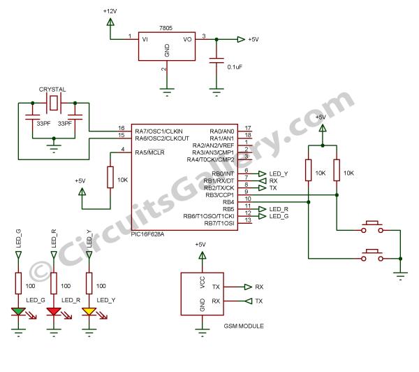
 Here I used PIC16f628A, which has only 18 pins but it has inbuilt UART module, this circuit can be used as GSM modem tester.
To test a GSM module/modem we have to connect it to PC and send AT command then check response, but it not possible when we buying this from a shop, this circuit make you to test GSM Module by simply pressing buttons to make call and send SMS.
Components Required
- PIC16F628A
- GSM modem SIM300
- IC 7805
- LED x3(Green, Red, Yellow)
- Resistor (100Ωx3, 10KΩx3)
- Capacitor (0.1µF, 33pfx2)
- Crystal 20MHz
- Push button
- Dot PCB
- Connecting wires
- 12V DC supply
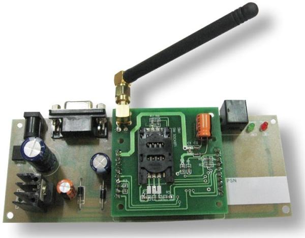
SIM300 GSM Module
Let’s have a brief look to the embedded wireless module SIM300,
- SIM300 GSM Modem is able to take any GSM network operator SIM card and behave just like a mobile phone with its own unique phone number.
- The RS232 interface lets modem to communicate with RS232 port of PC or compatible embedded system circuitry.
- Implementation of SMS controlled devices, Auto reply; remote control is possible via SIM300.
- The modem can be directly interfaced with microcontroller. It can be used to send, receive and process SMS/ call
- GPRS facility brings internet and FTP connection to your embedded project.
Popular Applications
- SMS based Remote Control Systems
- Security Applications and Sensor Monitoring
- GPRS/ TFTP Mode Remote Data Logging
Features
- Reliable for 24×7 operations
- Status of Modem Indicated by LED
- Easy to Use and cheap Cost
- Quad Band Modem supports all GSM operator SIM cards
For more detail: How to Interface GSM Module SIM300 with PIC 16F628A Microcontroller for sending SMS and making Calls
- What is the primary purpose of this circuit?
The circuit serves as a GSM modem tester that allows users to test the GSM module by pressing buttons to make calls and send SMS. - How does the PIC16F628A interact with the GSM module?
The microcontroller uses its inbuilt UART module to interface directly with the GSM modem for sending, receiving, and processing SMS and calls. - Can this system work without a PC connection?
Yes, unlike standard testing methods requiring a PC, this circuit enables testing the GSM module simply by pressing buttons. - What type of power supply is required for the project?
The project requires a 12V DC supply to operate the circuit components. - Which specific GSM module is recommended for this design?
The article recommends using the SIM300 GSM modem which supports quad band operations. - Does the SIM300 support internet connectivity?
Yes, the modem offers GPRS facility to bring internet and FTP connections to embedded projects. - What are the main applications for this setup?
Popular applications include SMS based remote control systems, security applications, sensor monitoring, and remote data logging. - How many LEDs are used to indicate the status of the modem?
The circuit utilizes three LEDs colored Green, Red, and Yellow to indicate the status of the modem.
