Summary of How-to: Bus Pirate v1, improved universal serial interface using PIC24FJ64GA002
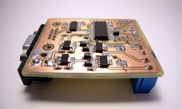
The Bus Pirate v1 is an updated universal serial interface tool designed to test new chips without writing code or designing PCBs. This version features a surface-mount design, cheaper components, software-resettable power supplies, and voltage monitoring capabilities. It includes a PIC24FJ64GA002 microcontroller, an RS-232 transceiver for PC connectivity, and enhanced pull-up resistor configurations with external voltage support.
Parts used in the Bus Pirate v1:
- Microchip PIC24FJ64GA002 28pin SOIC microcontroller (IC1)
- MAX3232CSE RS232 transceiver (IC2)
- 0.1uF bypass capacitors (C1, C2, C3, C4, C5, C6)
- 10uF tantalum capacitor (C20)
- 2K pull-up resistor (R1)
- Pull-up resistors on bus lines (R20-23)
- Row of jumpers (SV5)
- Power supply jack (J1) for 2.1mm DC barrel plug
- 3.3volt voltage regulator (VR1)
- 5volt voltage regulator (VR2)
- Five pin header (ICSP) for programming
- Vext terminal (X4) for external voltage
We use the Bus Pirate to interface a new chip without writing code or designing a PCB. Based on your feedback, and our experience using the original Bus Pirate to demonstrate various parts, we updated the design with new features and cheaper components.
There’s also a firmware update for both Bus Pirate hardware versions, with bug fixes, and a PC AT keyboard decoder. Check out the new Hack a Day Bus Pirate page, and browse the Bus Pirate source code in our Google code SVN repository.
We cover the design updates and interface a digital to analog converter below.
The Bus Pirate started as a collection of code fragments we used to test new chips without endless compile-program-run development cycles. We released it in a how-to and used it to demonstrate a bunch of serial interface ICs in our parts posts. This article introduces an updated design with new features and a bunch of improvements.
- Surface mount design
- Pull-up resistors on all bus lines with external voltage source
- Software resettable 3.3volt and 5volt power supplies
- Voltage monitoring of all power supplies
- An external voltage measurement probe
- Cheaper parts
Click for a full size schematic image (PNG). The circuit and PCB are designed using the freeware version of Cadsoft Eagle. All the files for this project are included in the project archive linked at the end of the article.
Microcontroller
We used a Microchip PIC24FJ64GA002 28pin SOIC microcontroller (IC1) in this project. The power pins have 0.1uF bypass capacitors to ground (C1,2). The 2.5volt internal regulator requires a 10uF tantalum capacitor (C20). The chip is programmed through a five pin header (ICSP). A 2K pull-up resistor (R1) is required for the MCLR function on pin 1. Read more about this chip in our PIC24F introduction.
RS-232 transceiver
An inexpensive MAX3232CSE RS232 transceiver (IC2) interfaces the PIC to a PC serial port. This chip replaces the expensive through-hole MAX3223EEPP+ used in the previous version of the Bus Pirate. The serial interface will work with a USB->serial adapter.
The original Bus Pirate has 3.3volt pull-up resistors on 2 pins, but most of our tests required additional external resistors. The updated design has pull-up resistors (R20-23) on the three main bus signals (data in, data out, clock) and the chip select (CS) pin.
A row of jumpers (SV5) connects each resistor to an external voltage supplied through the Vext terminal (X4). Through-hole resistors are used like jumper-wires to make the PCB easier to etch at home.
We couldn’t find an elegant way to control an arbitrary voltage pull-up resistor array from a 3.3volt microcontroller. If you have any ideas, please share them in the comments.
Power supply
VR1 is a 3.3volt supply for the microcontroller and RS232 transceiver. VR2 is a 5volt supply. Both require two 0.1uF bypass capacitors (C3-C6). J1 is a power supply jack for a common 2.1mm DC barrel plug. 7-10volts DC is probably the ideal power supply range.
For more detail: How-to: Bus Pirate v1, improved universal serial interface using PIC24FJ64GA002
-
What is the main purpose of the Bus Pirate v1?
To interface new chips without writing code or designing a PCB. -
Which microcontroller is used in this project?
A Microchip PIC24FJ64GA002 28pin SOIC microcontroller. -
How does the updated design handle pull-up resistors?
It uses pull-up resistors on all bus lines with an external voltage source via jumpers. -
What transceiver replaces the expensive one from the previous version?
An inexpensive MAX3232CSE RS232 transceiver. -
What is the ideal power supply range for the device?
7-10volts DC using a common 2.1mm DC barrel plug. -
Can the power supplies be controlled by software?
Yes, the design features software resettable 3.3volt and 5volt power supplies. -
What tools were used to design the circuit and PCB?
The freeware version of Cadsoft Eagle. -
Does the device support connection to a PC?
Yes, it interfaces with a PC serial port or a USB-to-serial adapter.