
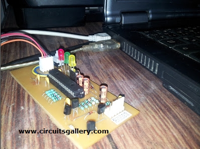
Summary of How to Build your Own USB PIC Programmer?
This article explains building a USB PIC programmer that programs Microchip PIC series (10F–30F) and 12Cxx EEPROMs using a PIC18F2550 MCU. It runs from USB power, generates 13V via voltage multipliers, supports ICSP, and uses USB PIC Prog software. Firmware is first burned into the PIC18F2550; jumpers select bootloader or programmer mode. No external supply or RS232 is needed. Common target PICs and components plus step-by-step usage are provided.
Parts used in the USB PIC Programmer:
- Microcontroller PIC18F2550
- Transistor BC548 (2 Nos)
- Transistor BC547
- Transistor BC557
- Diode 1N4148 (6 Nos)
- Resistors IK (7 Nos)
- Resistor 100K
- Resistor 470 (2 Nos)
- Resistor 1M
- Resistor 470K
- Resistor 330 (3 Nos)
- Capacitor 0.01uF (3 Nos)
- Capacitor 2.2uF (2 Nos)
- Capacitor 10uF
- Capacitor 22pF (2 Nos)
- Crystal 8MHz
- USB connector
- 5-pin header (2 Nos) for ICSP
This DIY PIC programmer is a continuation of our PIC programming basics tutorial. By using this USB PIC programmer, you can program microchip PIC series of 10F, 12F, 16F, 18F, 24F, 30F. This is also an EEPROM programmer as it supports 12Cxx EEPROM. The main component of this PIC microcontroller programming circuit is a PIC182550 microcontroller which controls the overall circuit. Serial port PIC programmers are the widely used PIC chip programmer Kit, but since laptops have no RS232 ports they require an USB to RS232 converter.
Recommended for you:
- PIC microcontroller Beginner’s guide: Basic connection circuit
- How to burn or program PIC Microcontroller
Now one of the main advantages of this circuit is that it does not require any external power supply, instead it uses USB power. It generates programming voltage of 13V through voltage multipliers. Linux PIC programmer software is also available for burning. You can program micro controller like pic16f84a, pic16f877a, pic18f4550, pic16f628a etc. and make your micro controller programming easier.
Circuit diagram of PIC Chip Programmer
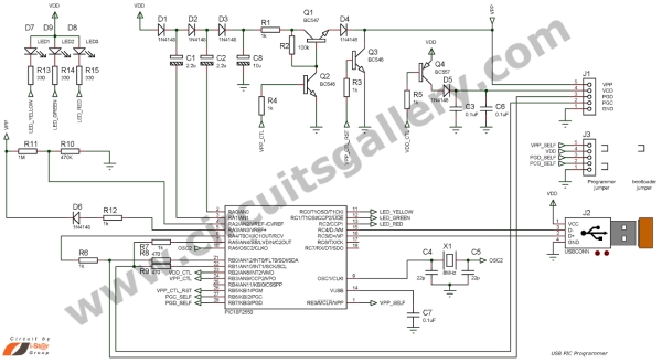
Components Required
- Microcontroller PIC 18F2550
- Transistor (BC548-2Nos, BC547, BC557)
- Diode IN4148(6Nos)
- Resistor(IK-7Nos, 100K, 470-2Nos, 1M, 470K, 330-3Nos)
- Capacitor(0.01uF-3Nos,2.2uF-2Nos, 10uF, 22pf-2Nos)
- Crystal 8MHz
- USB Connector
- 5-Pin Header (2Nos)
Step by Step procedure
-
- PIC 18F2550 has an inbuilt USB port which makes PC interfacing much easier.
- First a firmware should be burnt to PIC 18F2550 using any PIC programmer and then connect the jumper as in the circuit diagram.[wpdm_file id=3]
- The jumper connection decides the mode of the programmer, i.e. boot loader mode or programmer mode. Boot loader is used to upgrade your firmware and programmer mode is to burn the PIC microchip.
- Next we need software to burn our PIC, USB PIC Prog is suitable for this hardware. Download USB PIC Programmer Software from the following link
File Name: x86 (32 Bit) USB_PIC_Programmer_Software_USB_PIC_Prog.rar
x64 (64 bit) USB_PIC_Programmer_Softwarex64
- Now connect the circuit to the USB port of your PC and open hex file to PIC programmer software.
- Connect any PIC microchip through the ICSP (In Circuit Serial Programming) Header, it include VPP, VDD, PGD, PGC, GND.
- Now you are done with it. So what are you waiting for? Start burning PIC microcontroller.
Components Pin Out


Source : How to Build your Own USB PIC Programmer
- What microcontrollers can this USB PIC programmer program?
It can program Microchip PIC series including 10F, 12F, 16F, 18F, 24F, 30F and specific chips like PIC16F84A, PIC16F877A, PIC18F4550, PIC16F628A. - Does the circuit require an external power supply?
No. The circuit uses USB power and generates the 13V programming voltage through voltage multipliers. - Which main microcontroller controls the programmer circuit?
The PIC18F2550 microcontroller controls the overall circuit. - How do you switch between bootloader and programmer modes?
By setting the jumper connections as shown in the circuit diagram; the jumper decides bootloader or programmer mode. - What software is recommended for burning PICs with this hardware?
USB PIC Prog software is recommended and available for download in 32-bit and 64-bit versions. - How is the target PIC connected to the programmer?
The target PIC is connected via the ICSP header which provides VPP, VDD, PGD, PGC, and GND. - Is RS232 or USB-to-RS232 required for this programmer?
No. Since the PIC18F2550 has a built-in USB port, no RS232 or USB-to-RS232 adapter is required. - What must be done before using the programmer with the PC?
First burn the firmware into the PIC18F2550 using any PIC programmer, then connect the circuit to the PC USB port and open the hex file in the PIC programmer software.
