Summary of GPS based speedometer using pic microcontroller
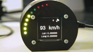
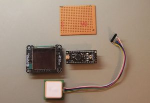
This article details a DIY GPS Speedometer project built to replace a faulty car speedometer. The creator selected the DFRobot Dreamer Nano V4.1 microcontroller, UBX-G7020-KT GPS module with an integrated antenna, and an OLED 2828 Display Module. Power is supplied via the car's cigarette lighter socket. The system includes 10 LEDs (7 green, 3 red) for visual feedback and features a custom 3D-printed casing. Components are assembled on a perfboard, with the display connected last to facilitate wiring.
Parts used in the GPS Speedometer:
- DFRobot Dreamer Nano V4.1 microcontroller
- UBX-G7020-KT GPS module with integrated antenna
- OLED 2828 Display Module
- Car cigarette lighter socket power source
- Custom 3D printed casing
- 10 LEDs (7 Green and 3 Red)
- Perfboard for assembly
My company car that I normally drive tends to have a “small” problems from time to time, the speedometer fall to 0 Km/h when driving (after some time it resumes again).
Normally this is not a big issue since if you know how to drive a car, you are not, I hope, always looking to the speedometer. You now more or less the speed that you are driving. The problem present it self when you need to decrease speed to the road limit that you are entering and you notice that “the speedometer is down”.
This presented like a good opportunity to build a new project, “The GPS Speedometer”. Of course the ideal solution would be, really repair the car or use a normal GPS or use an app with this function but what would be the fun in this 🙂
Step 1: Components
Microcontroller
I selected theDFRobot Dreamer Nano V4.1 because it has a usb plug that I can use for power and a compatible breadboard pinout.
Check DFRobot wiki page for more info regarding this microcontroller
GPS
I’m using the UBX-G7020-KT, that comes with an integrated antenna and allows to change the refresh rate until 10Hz(for this project this featuring can came in hand).
On the DFRobot wiki page you will find more info regarding it.
Display
I wanted to have a good display without “blowing” the budget, my choose was the OLED 2828 Display Module. Check again the wiki page for some more info.
Power
The power for the system will be provided by the car cigarette lighter socket.
Casing
This time I when for designing a casing and 3D printing it.
Step 2: Connect the Components
The design with the LED’s was not my first choice. So initially I designed the schematic without LED’s
But in the end I added 10 LED’s (7 Green and 3 Red’s).
I forgot to take some pictures of the assembly process, so what I can say is that everything is assembled in the prefboard, in one side is the oled display and in the other the microcontroller and connections. In order to make this easy leave the oled display for last since some of the connections will be done on its back.
Source: GPS based speedometer using pic microcontroller
- Why was this GPS Speedometer project created?
The project was built because the author's company car speedometer occasionally failed by dropping to 0 Km/h while driving. - Which microcontroller was selected for the build?
The DFRobot Dreamer Nano V4.1 was chosen because it has a USB plug for power and a compatible breadboard pinout. - What specific GPS module is used in this design?
The UBX-G7020-KT is used, featuring an integrated antenna and a refresh rate capability up to 10Hz. - How does the system receive its power?
The power for the entire system is provided through the car cigarette lighter socket. - What type of display module was installed?
An OLED 2828 Display Module was selected to balance performance with budget constraints. - How many LEDs were added to the final design?
The final design includes 10 LEDs, consisting of 7 green ones and 3 red ones. - On what material are the components assembled?
All components are assembled on a perfboard. - What method was used to create the project enclosure?
The casing was designed and created using 3D printing. - When should the OLED display be connected during assembly?
The OLED display should be left for last because some connections must be made on its back.