Summary of Function Generator using PIC16F870 microcontroller
This article describes a DIY multifunction signal generator built around a PIC16F870 microcontroller. It generates various waveforms like sine, triangle, and square waves using software algorithms and an R/2R resistor ladder for digital-to-analog conversion. The system features a 256-byte lookup table for sine waves and operates at 20 MHz to produce clean frequencies up to over 60 kHz. User interaction is minimal, relying on three LEDs for status, two buttons for control, and a rotary encoder for selection, requiring an oscilloscope for visual verification of the output signals.
Parts used in the Function Generator:
- PIC16F870 microcontroller
- R/2R resistor ladder network
- Low-pass filter
- Three function indicator LEDs
- Three step rate indicator LEDs
- RATE button
- Select button
- Adjustment control (rotary encoder)
- Oscilloscope (for verification)
Sine Triangle Square Saw Burst Sweep Noise – runs on a PIC16F870
After the recent demise of our multifunction signal generator, we decided to make one of our own. The circuit uses a PIC16F870 (about $3), an R/2R resistor ladder network (for a real fast and cheap D/A), and a few other parts.
You can check out the schematic and the current source file. Also the object (hex) file. All of the sine wave functions utilize a full 256 byte by 8 bit lookup table. Contrary to what you may have heard elsewhere, it is possible to use a full memory page in the PIC for a lookup table – check it out.
The only real elaboration was the design of the low-pass filter. With the present design running on a 20 mhz clock, you can get over 60 khz of very clean sine waves. The frequency is adjustable in 1, 25, and 500 hz steps. The unit produces accurate frequencies down to 1 hz.
Since all of the waves are generated in software, the ‘user interface’ had to be kept to a minimum. Three LED’s indicate the functions (which vary depending on the type of wave being generated). Three more LED’s indicate the step rate of the adjustment control. Pushing the RATE button advances to the next step rate and pushing the select button goes to the next function.
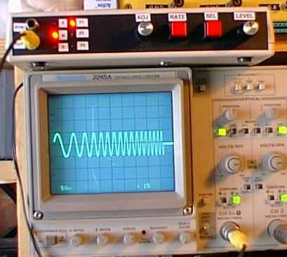
The wave function itself is selected by holding down the select button while rotating the adjustment control. Since there is no visible indication of the wave type or frequency, you need to have a scope hooked up to see what you are doing.
Source : Function Generator using PIC16F870 microcontroller
- How does the circuit generate digital to analog signals?
The circuit uses an R/2R resistor ladder network which serves as a fast and cheap D/A converter. - What is the size of the lookup table used for sine waves?
All sine wave functions utilize a full 256 byte by 8 bit lookup table stored in the PIC memory. - Can the unit produce accurate low frequencies?
Yes, the unit produces accurate frequencies down to 1 hz. - How many LED indicators are used for the user interface?
The design uses six LEDs total: three indicate the functions and three indicate the step rate of the adjustment control. - How do you select a specific wave function?
You must hold down the select button while rotating the adjustment control to change the wave function. - What is required to see what the unit is doing visually?
Since there is no visible indication of the wave type or frequency, you need to have a scope hooked up to see what you are doing. - What clock speed does the design run on?
The present design runs on a 20 mhz clock. - What frequency steps are available for adjustment?
The frequency is adjustable in 1, 25, and 500 hz steps. - What is the maximum frequency capability mentioned?
With the current design, you can get over 60 khz of very clean sine waves. - Are the wave functions generated in hardware or software?
Since all of the waves are generated in software, the user interface had to be kept to a minimum.