Last year I bought this Etch-Set For Electronic Circuits from Jaycar with the intention of having a go at making my own printed circuit boards (PCBs). I’d had lots of experience working with those experimenter’s Stripboards and Perfboards, which had been more than sufficient for most of the fiddling I did in the past, however I was always intrigued by the idea of rolling my own PCBs although I lacked the resources back then to make it happen.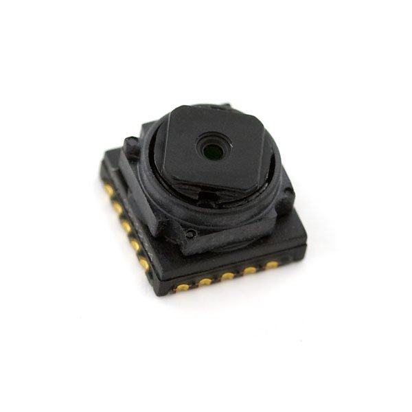
After acquiring the kit, the project I had in mind for the PCB – a PIC-based Bluetooth controlled car (more on this later) – ended up being implemented using Stripboard since in a sense it was just a proof-of-concept and these prototyping boards are great at allowing you to explore an idea without having a concrete design in mind. If you don’t mind soldering and you hate the restrictiveness of a solderless breadboard then Stripboards are perfect. You can pretty much place components where ever you like knowing that you can easily run jumpers to make connections or where necessary, create discontinuities in the parallel strips of copper with a small drill bit. I have found that with these boards, how condense the components can be laid out is only limited by one’s imagination.
Anyhow, two months ago I finally decided to start my voyage into the wonderful world of DIY PCB fabrication, mostly because the project I had in mind could be implemented in no other way. Last April I had bought a CMOS VGA camera sensor off SparkFun with the crazy idea of incorporating it into my Bluetooth car. What I was really after was the JPEG version which was already conveniently mounted on a PCB with a TTL serial interface, however these were out-of-stock at the time so I thought I’d be a bit ambitious and try this cheaper alternative. So, knowing the only way I could make use of this surface mounted device (SMD) was to first solder it to a breakout board I set out to design and fabricate my very first PCB from scratch.
Now this sensor had been around for a while and quite a few people have already been through the process of creating breakout boards for it, for example this dude here. However I was determined to do this the hard way and design my own using one of the freely available PCB CAD software online. To make things even more interesting, it turned out that no package library with a component matching the device’s footprint was available online from Toshiba (the device manufacturer) so for starters I would have create that from the device’s form-factor drawings in the specifications documentation.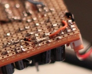 As it turned out, I did get there in the end, and with a great deal of effort and trial and error I managed to create the simple breakout board on the right. To be honest, I was so pleased with the result that I was hesitant to mount the device for fear of making a mess of it. I thought maybe I could just frame it and keep it for motivation.
I’ve provided a link to the Eagle files here for anyone who might find them useful. In my next post I’ll go through the steps I followed to create this, my first PCB.
For more detail: Fun with PCBs