Summary of Frequency Counter using PIC16F877A Microcontroller
This project describes a PIC16F877A-based frequency counter using Timer1 to count input signal edges and Timer0 to create a 1 second measurement window. A 4 MHz crystal yields a 1 MHz instruction clock; Timer0 overflows are counted (3906 overflows + final 64-cycle adjust) to make an exact 1 s interval. The LCD (HD44780, 2-line, 4-bit mode) displays the measured frequency in Hz. Source code (C and hex) and hardware notes are provided; input is TTL and max tested frequency is ~20–50 MHz depending on PIC pin limits.
Parts used in the PIC frequency counter:
- PIC16F877A microcontroller (or any PIC with TMR0 and TMR1)
- 4 MHz crystal oscillator
- Two crystal load capacitors
- 2-line HD44780 compatible LCD (used in 4-bit mode)
- LED (status/alive indicator)
- ICSP connector for in-circuit programming
- TTL level input signal source
- Supporting passive components (wiring, power supply, connectors)
A frequency counter is a useful addition to an engineer’s toolbox and you can create the design described on this page for free. All you need is a PIC microcontroller (or any microcontroller that has a high speed timer input module) and a 2 line LCD display (the standard HD44780 one is the one used here).
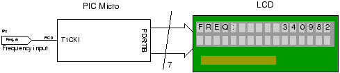
This PIC frequency counter project uses an LCD to display the frequency and PIC timer 1 to measure the input signal and Timer0 to measure the timing period.
It uses Timer 1 in 16 bit counter mode to count the input signal edges and overflows of the counter are accumulated to give the total count in multiples of 65536.Adding the current value of the counter at the end gives the total count.
The crystal oscillator is chosen to be 4MHz (Fosc) so that the processor internal clock is 1MHz (Fosc/4). All you do is count 1e6 processor clocks (Timer0) to give a 1second count period.
Since the measurement time is 1 second the final count is actually the frequency of the input signal i.e. number of input periods counted in 1 second is the frequency in Hz.
Using the 1 second measurement time also gives a frequency resolution of 1 Hz.
Specification: LCD frequency counter circuit
| Min frequency | 1Hz |
| Max frequency | ~50MHz (limited by input pin characteristics).(Tested using TTL oscillator at 20MHz). |
| Input signal level | TTL |
Note: The exact maximum operating frequency is determined by the PIC input pin characteristic.
| Compiler | Mikroelectronika MikroC Compiler Free! |
| Target | 16F877A (retargetable to other PICs that have TMR1) |
| Software level | Advanced. |
| Software notes | Interrupt Driven counting and time measurement. |
| Hardware level | Easy. |
| Hardware notes | None |
| Project version | 1.03 |
| Project files | Enter your details to get the Download Link and get the microcontroller newsletter:
(Note: Your email is safe it will never be sold or rented). Note: Check your email for the project code download link. |
For the general theory of operation of this circuit and notes on frequency counting of this pic frequency counter click here.
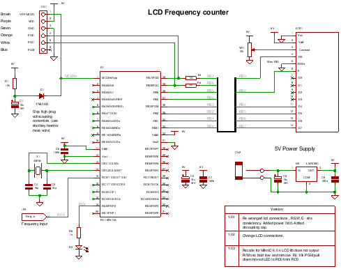
PIC frequency counter schematic using LCD and TMR0 and TMR1.
(Click diagram to open a pdf.)
Pic frequency counter Hardware
The hardware is simple and the main blocks are shown in the diagram below.
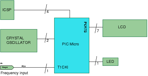
The LCD is used in 4 bit mode interface so you only need 4 data lines and three control lines and it then fits into a single 8 bit port.
The crystal oscillator is simply a crystal and two capacitors connected to the PIC oscillator port at OSC1 and OSC2. The capacitors can both be fixed at the same value unless you want to tune it using a frequency reference. If you don’t have an accurate reference then use fixed capacitors.
The PIC micro can be any type that has Timer 0 and Timer 1 hardware modules and and has enough memory to hold the program ~1.6k words.
The LED is toggled to indicate that the processor is alive – so if there is no input signal you can tell that the software is working. Also if there is no input signal the the LCD displays a flashing zero.
You can program the PIC in circuit through the ICSP connector in circuit.
Description
To time a 1 second count Timer0 is used. Since the main clock is running at 4MHz then the processor clock (Fosc/4) is 1MHz which is the rate that Timer0 is set-up to use i.e. the internal clock. Therefore we need to get a 1 second count using that timer. Since the timer is only 8 bits long you can use the fact that an interrupt is generated when it overflows – you can then count these overflows to get near to 1e6 counts.
Since the overflow occurs every time that the counter passes 256 we need to count 1e6/256 overflows
1e6/256 = 3906.25
We can only count integer overflows so must manipulate the last count to get the exact time. So we need the modulus of 1e6 and 256:
1e6 % 256 is 64 (0.25*256 is 64).
The interrupt routine starts off after being zeroed by counting 3906 overflows, it then controls a flag variable (do_TMR0_end_count) that indicates this is the last overflow for which the Timer0 value is set to overflow after 64 Fosc/4 cycles:
TMR0 = 256-64+2; // 2 cycles lost when writing to TMR0 so add 2.
At the end of the last overflow the values of Timer1 are captured to:
st_TMR1L
st_TMR1H
st_TMR1_ovfl
An LCD update request is sent from the interrupt routine to the main routine by setting a flag (update_LCD) and the main routine then uses ltoa to calculate and output the frequency measurement to then display on LCD.
PIC frequency counter Software
Project files for the PIC frequency counter
Compiler project files
frequency_counter_4MHz_LCD_TMR1.mcppi
This is the main project file.
There are other files since MikroC version 6.0.4 seems to need a lot more than V5! just keep them in your project folder.
C Source files.
Frequency_counter_4MHz_LCD_TMR1.c
ltoa.c
Header files.
bit.h
ltoa.h
Output files
Frequency_counter_4MHz_LCD_TMR1.hex
For a tutorial on compiling these files click here.
You only need to recompile the pic frequency counter files if you want to change the source code or examine how the code works using the built in simulator since the hex file to program the chip is included in the download.
Brief description
- frequency_counter…c : contains the code start point (in routine ‘main’) and the interrupt routine.
- ltoa.c contains a long to ascii converter used for display of the frequency count.
- bit.h : contains macros for bit manipulation.
All other header files contain prototypes.
PIC frequency counter code operation.
The code uses the built in LCD driver routines which are automatically included by the compiler. Note automatic include is unusual but it seems to work well in mikroC.
Interrupts are not used only the flags that can be polled (timer overflow) are activated.
frequency_counter_4MHz_LCD_TMR1.c
This file contains the port initialization, interrupt and main routine.
After initialization the code enters an endless loop where it continuously performs a measurement and display operation. After an accurate 1 second delay the counter result is processed and displayed on the LCD.
The main operation of this code is within the interrupt routine that both counts the input edges and obtains an accurate 1s time by counting the edges of the internal oscillator clock (Fosc/4).
Interrupts
The most important part of this counter is the interrupt() routine. This is where all the action and decisions are made.
The interrupt code for Timer1 is very simple and all it does is increment a long variable for counting multiple input events.
The more tricky interrupt code, for Timer 0, counts time as described above. It counts 3906 overflows followed by a single 64 cycle count to reach a time of 1 second after which it captures the event count and then triggers an update to the LCD to calculate and display the frequency. The update triggers the actions in main().
bit.h
This contains macros for bit manipulation which should be compiler independent.
Source : Frequency Counter using PIC16F877A Microcontroller
- What microcontroller is used in the project?
The project targets the PIC16F877A but can be retargeted to other PICs that have TMR0 and TMR1. - How is the 1 second measurement interval generated?
Timer0 runs from the 1 MHz processor clock; the code counts 3906 overflows and a final 64-cycle adjusted overflow to create an exact 1 second interval. - What timer counts the input signal edges?
Timer1 in 16 bit counter mode counts the input signal edges, with overflows accumulated for totals beyond 65535. - What display is used to show the frequency?
A standard 2-line HD44780 compatible LCD is used in 4-bit mode to display the frequency. - What is the input signal level supported?
The input signal level is TTL. - What is the frequency resolution of the counter?
Using a 1 second measurement time gives a resolution of 1 Hz. - What is the approximate maximum measurable frequency?
The maximum is approximately 50 MHz but the exact limit depends on the PIC input pin characteristics; testing was done at 20 MHz TTL. - What compiler is used for the project code?
The MikroElektronika mikroC compiler (free) is used for the project files. - How is the LCD updated after a measurement?
The interrupt routine captures Timer1 values and sets an update_LCD flag; the main routine polls this flag, converts the count using ltoa, and updates the LCD. - Can the PIC be programmed in circuit?
Yes, the PIC can be programmed in circuit through the ICSP connector.