Summary of 50MHz 7 segment frequency counter using PIC16F877A
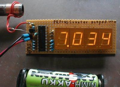
This article describes a 50MHz frequency counter circuit using a PIC16F877A microcontroller. It utilizes TMR1 in 16-bit mode to count input signal edges, accumulating overflows for high-frequency measurements. The design features an eight-digit seven-segment display multiplexed by a 4017 Johnson counter, refreshed every millisecond to prevent flickering. The system provides 1Hz resolution with a one-second measurement gate and supports TTL input signals.
Parts used in the 50MHz Frequency Counter:
- PIC16F877A microcontroller
- TMR1 timer module (16-bit counter mode)
- Eight seven-segment displays
- 4017 Johnson counter
- Transistors (for driver circuits)
- Crystal oscillator
- Two capacitors (for oscillator tuning)
- PORTA and PORTD I/O pins
In the same way as the LCD project this frequency counter circuit uses TMR1 in 16 bit counter mode to count the input signal edges. Counter overflows are accumulated to give the total count in multiples of 65536. Adding the current value of the counter at the end gives the total count.
Specification of the frequency counter circuit
| Min frequency | 1Hz |
| Max frequency | ~50MHz (limited by input pin characteristics). |
| Input signal level | TTL |
The major difference in this project is that the display must be continuously refreshed so that your eye is fooled into thinking that display as is not flickering (persistence of vision).
For this frequency counter circuit project the display is refreshed every millisecond which is excessive – but does work. This refresh rate was chosen due to the timing period of the gate loop (999us) and allows easier constant time operation. Your eye only needs a refresh rate of about 50Hz or 20ms.
Pushing the refresh rate higher also shows you how to split the processing of a machine code algorithm, in the C environment, into several pieces so that the display can be refreshed at an approximate 1ms rate.
Just as in the LCD project the measurement time is 1 second the final count is actually the frequency of the input signal and again using the 1 second measurement time gives a frequency resolution of 1 Hz.
Note: The exact maximum operating frequency is determined by the PIC input pin characteristic.
Frequency counter circuit Test routines
Once constructed you can test the wiring out using the following two files e.g. if the 1st download file does not appear to work:
These tests will also test out a system using individual 7 segment displays.
| Frequency counter circuit:Test wiring 1 | Download here. |
| Frequency counter circuit:Test wiring 2 | Download here. |
Test wiring 1 : Outputs constant digits to the display and reads “12345678” from left to right. You can use this test to see if PORTD and each transistor driver is connected correctly.
Test wiring 2 : Outputs a shifted digit set from 1-8 to test PORTD connections to each 7 segment. Just observe each digit and make sure it goes through each number 1 to 8.
Compilation
For a tutorial on compiling these files click here.
You can recompile the frequency counter circuit files if you want examine code operation (using the built in simulator) or change the source code. Note the hex file is contained in the download.
For the general theory of operation of this circuit and notes on frequency counting for this frequency counter circuit click here.
PIC frequency counter circuit Hardware
The main circuit blocks of the frequency counter circuit are shown in the diagram below.
The 8 seven segment displays are multiplexed using a Johnson counter (4017) that activates a single output after each clock pulse. Port A drives the reset line and clock signal to the 4017 and transistors at the outputs of the 4017 are connected to the common cathode of each seven segment display. This lets the micro turn on each display sequentially. Port D drives the segment enable lines to control the character displayed.
The crystal oscillator is simply a crystal and two capacitors connected to the PIC oscillator port at OSC1 and OSC2. The capacitors can both be fixed unless you want to tune it using a frequency reference. If you don’t have an accurate reference then use fixed capacitors.
For more detail: 50MHz 7 segment frequency counter using PIC16F877A
- How does the circuit handle frequencies exceeding 65536?
Counter overflows are accumulated to give the total count in multiples of 65536, adding the current counter value at the end. - What refresh rate is used for the display?
The display is refreshed every millisecond to ensure persistence of vision and avoid flickering. - What is the frequency resolution of this circuit?
Using a 1 second measurement time gives a frequency resolution of 1 Hz. - How are the seven segment displays activated?
A 4017 Johnson counter activates a single output after each clock pulse to turn on each display sequentially. - What type of input signal level does the circuit support?
The circuit accepts TTL input signal levels. - What determines the exact maximum operating frequency?
The exact maximum operating frequency is determined by the PIC input pin characteristic. - Can the capacitor values be changed for tuning?
Capacitors can be fixed unless you want to tune the crystal oscillator using a frequency reference. - How can I test if the wiring is correct?
You can use Test wiring 1 to check PORTD and transistor drivers, and Test wiring 2 to verify digit shifting from 1 to 8. - Does the project allow code examination?
Yes, you can recompile the files to examine code operation using the built-in simulator or change the source code.