
Summary of Fluke/Philips PM66xx Frequency Counter OCXO Upgrade
Summary: The author upgraded a Philips PM6674 frequency counter by designing an OCXO timebase board compatible with Fluke/Philips PM66xx modules. The project uses a Recom 78C5.0 DC-DC converter to derive a stable 5V from the counter's noisy ~27–30V rail, filters with electrolytic and ceramic capacitors, and a CTS 10 MHz OCXO providing a 4V reference and ~1.4Vpp sine output matched to the counter's 1Vpp input spec.
Parts used in the OCXO Upgrade for Philips PM6674:
- Philips PM6674 frequency counter (host device)
- Recom 78C5.0 DC-DC converter (5V regulator module)
- CTS 10 MHz OCXO (oven-controlled crystal oscillator)
- Electrolytic capacitors (input/output filtering)
- Ceramic capacitors (input/output filtering)
- PCB and connector compatible with PM66xx OCXO module header
Introduction
A few months ago I purchased a Philips PM6674 frequency counter on eBay. It’s an older 9 digit counter with two channels that has a maximum input frequency of 550MHz. The design feels dated compared to more modern counters, such as my Agilent 53131A. However, it is still a fully functional piece of lab equipment with a simple user interface and compact design. I often prefer older counters for day-to-day use because I don’t have to fuss with complicated menu-based interfaces and features that I don’t need. (Set the gate time on a 53131A and count how many button presses it takes).
My counter came with the standard XO timebase option, which has fairly poor specs for stability and drift. It is difficult to trim precisely with the single-turn trimmer capacitor on the board. For most testing in my lab I use an external reference from a GPSDO, but it is still nice to have an accurate timebase available in the counter if I need to take it somewhere and do testing away from the bench.
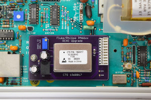
Previously I posted about an OCXO upgrade I made for my Racal-Dana 1992. The fun of designing a similar upgrade for the Philips counter was one of my motivations for purchasing it. My upgrade board is roughly equivalent to the original PM9691 OCXO module, and it should be compatible with any Fluke/Philips counter that is capable of using that option. Fluke/Philips PM66xx Frequency Counter OCXO Upgrade
Designing an OCXO Upgrade
Creating a timebase upgrade board for the PM6674 was a bit more involved than the process for designing the Racal-Dana upgrade. That counter had a clean 5V supply available on the header where the timebase board connected, which was exactly what I needed for the OCXO. The header for the OCXO module in the Philips counter also has a 5V rail. However, that rail does not stay active when the counter is in standby. The original Philips OCXO modules operated from the 24V rail, and I had to use that for my own upgrade. In my counter, the “24V” rail actually runs at about 27V, and drifts up to 30V when the counter is in standby. There is also a substantial amount of ripple.
I opted for a Recom 78C5.0 DC-DC converter to get the 5V I needed to power my board. This is a nice little module with a pinout that mimics the 7805 linear regulator. It has good specs for efficiency (as high as 96%) and was very easy to implement on my board. I used a combination of electrolytic and ceramic capacitors on the input and output for filtering.
With power taken care of, the remainder of the board is very simple. I used the CTS 10MHz OCXO that I did a teardown on and reverse-engineered the schematic for. This OCXO has a 4V reference available on one of the pins, so I did not need to add a separate reference IC to the design. Additionally, the CTS OCXO has a ~1.4Vpp sine wave output, which is quite compatible with the Philips counters. The input spec for the internal reference signal is 1Vpp into 1kohm.
For more detail: Fluke/Philips PM66xx Frequency Counter OCXO Upgrade
- Why upgrade the PM6674 timebase?
The stock XO has poor stability and drift, and the OCXO provides a more accurate internal reference when an external GPSDO is not available. - Can the PM6674 header provide 5V for an OCXO?
The header has a 5V rail but it is not active in standby, so the design uses the 24V rail instead. - What supply voltage does the counter provide for the OCXO module?
The original OCXO modules used the 24V rail, which in this counter measures about 27V and can rise to 30V in standby with substantial ripple. - How is 5V generated for the upgrade board?
A Recom 78C5.0 DC-DC converter is used to derive a stable 5V from the 24V rail. - What capacitors are used for power filtering?
A combination of electrolytic and ceramic capacitors is used on the DC-DC input and output for filtering. - Which OCXO was used in the upgrade?
The CTS 10 MHz OCXO that the author reverse-engineered is used. - Does the CTS OCXO need an external reference IC?
No, the CTS OCXO provides a 4V reference on one pin, so no separate reference IC was required. - What is the output signal level of the CTS OCXO?
The OCXO outputs about a 1.4Vpp sine wave, which is compatible with the counter input spec of 1Vpp into 1kohm.

