This is a small dev board I designed to make experimenting with and deploying the ESP8266 ESP-03 modules a bit easier. As well as breaking out all the pins to 2.54mm headers it has a position to fit either a DS18B20 temperature sensor or a DHT22 temperature/humidity sensor plus the required pull up resistor. It can be powered from 3.3V or 5V+* if the regulator is fitted and there is a footprint for a micro USB connector if required.
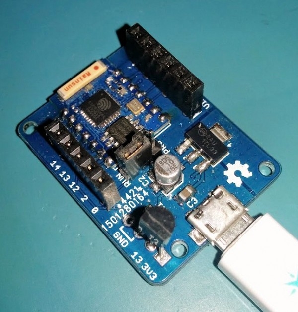 *The regulator I used is good for up to 18V but I don’t know how far you would be able to push it with only the small area of PCB that is used as a heatsink. I would imagine it will be OK to at least 9V.
A 3 way pin header allows a jumper to be moved to switch between normal running mode and flash programming mode. With the jumper in the RUN position GPIO0 is connected to the header marked 0 and in the PRG position GPIO0 is grounded. It needs to be powered up with the jumper in the PRG position to enable programming mode.