
High-level Design
The goal of this project is to create an electronic flute. The musical instruments like keyboards, guitars, etc. have adjustable keys in order to play sounds at different scales. However, flutes are designed for only one scale and therefore need to be changed to play music on another scale. Hence, our electronic flute will allow the user to change the scale of the song without the need of changing the complete instrument. In addition, the electronic flute is able to adjust the volume of the sound. During the time when users do exercise at home, users can put on headphones to avoid influencing neighbors. During the performance time, the user can just turn on the volume of the sound without using a microphone.
Flute Background
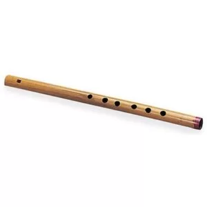
A typical bamboo flute has total of seven holes as shown in the picture. One of these holes is for the inlet of wind. The strength of air blown into this hole determines the octave of the note. The greater strength wind play the higher octave note and the lesser strength wind would play same note from lower octave. The other six holes need to be covered with the fingers in order to play different notes. The portion of the holes covered also matters in generating sounds. For example, if a fully covered hole generates a note at C scale, the half open hole can generate a C minor. To mimic the typical bamboo flute, our electronic flute was designed with 12 Charge Time Measure Unit (CTMU) to simulate the sounds with whole covered or half covered holes in bamboo flute. To adjust the octave, one microphone and one CTMU were implemented on our electronic flute.
Basic Logical Structure
The sensing for the capacitance touch switch will be done using CTMU in PIC32 controller. The high octave was produced using the on chip PIC32’s ADC unit connected to the microphone. The low octave was generated using CTMU which mounted at where the player’s mouth can touch while playing the flute. The sound signal will be sent to DAC via SPI and output of DAC will be supplied to the Speakers or headphones. The user is able to select different scales based on two buttons and visualize the scale selection feedback given by TFT LCD.
Hardware and Software Trade-Offs
The primary motive of the project is to synthesize signals in PIC32 in order to generate the sounds which are as close as to a real flute as possible. In order to maintain our primary goal, the team should spend more time on sound synthesis section. Considering the flute should be convenient to play, the weight of the flute should keep small. Therefore, the speaker and power supply(battery) cannot be put on the flute.
Benchmarking
The multi-scale electronic flute mimics the real flute playing. Unlike the traditional flute using the air flow generating sound, our multi-scale electronic flute uses the software program to generate the flute sound based on the sound frequency. Considering the issue that the traditional flute cannot generate a very loud sound, our multi-scale electronic flute connected with speakers that can amplify the sound. Also, it can connect with headphones to support practicing flute playing individually.
Rhino resonator and flute crown is a patented flute optimization design. This technology improves sound generation, amplified and stabilize the flute sound. However, our multi-scale electronic flute considered more than amplifying flute sound. The electronic flute can also support up to eleven different scales of operation. In this case, the flute players can use one multi-scale electronic flute instead of needing eleven different flutes for each scales.
In addition to that, the TFT display was mounted on the side of the flute showing the player the scales that the player is currently playing. This new design method is rare in electronic flute market.
Software Design
- Interrupt Service Routine (ISR)- uses additive synthesis to output the sound to the DAC
- Display Thread- displays the current scale that the flute is playing
- ADC/CTMU Thread- runs CTMU and reads the ADC value of the switches
- Frequency Thread- determines what note to play
- Debouncing Thread- denounces the two buttons that change the octave and key of the flute
The code for this project can be downloaded from the Appendix section.
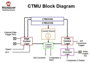
Charge Time Measurement Unit (CTMU)
The Charge Time Measurement Unit (CTMU) is used to create the thirteen capacitance touch switches for the flute. The CTMU is a constant current source that works in conjunction with the analog-to-digital (ADC) channels. Since the CTMU provides a constant current source, we know that the ADC value will change based on whether a finger is touching the capacitive switches. We determined a threshold for the adc value, which was 950, that we could use to determine if a finger was touching any of the twelve buttons.
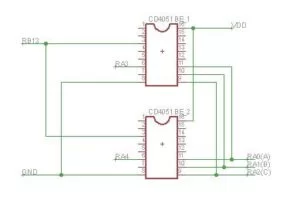
One small issue we ran into when we wanted to implement CTMU for all the thirteen switches is that there were not enough ADC channels on the pic32. A simple solution to this problem was incorporating 8 by 1 multiplexers. We used two multiplexers that were both connected to the ADC channel AN11. Then, by controlling the chip select of the muxes, we made it so that only one mux was turned on at a time and only one line of either of the muxes is connected to the ADC pin.
ADC/CTMU Thread
As stated above, the main purpose of the ADC/CTMU thread is to read the ADC value of the thirteen capacitance touch switches to determine which switches are being pressed. The thread starts off by setting the ADC channel to AN11 which is the channel that both muxes are connected to. Next, we turn on the CTMU and then go through a for-loop for each of the capacitive switches. In the for-loop, we must first determine which mux should be turned on using chip-select so that the correct mux is connected to the ADC channel. The first 8 values in the for-loop correspond to the first mux and the rest of the values correspond to the second mux. Next, the following code shows how close the discharge switch to drain the circuit of any charge.
CTMUCONbits.IDISSEN = 1; // start drain of circuit
PT_YIELD_TIME_msec(1); // wait for discharge
CTMUCONbits.IDISSEN = 0; // End drain of circuit
Discharging the circuit is followed by charging the circuit for exactly 2 microseconds as seen in the following code:
// start charging and wait 2 microsecs
CTMUCONbits.EDG1STAT = 1;
wait40;wait40;
CTMUCONbits.EDG1STAT = 0; // end charging
Playing the Correct Frequency
The first step to producing the sound of a flute was ensuring that we had all the right frequencies for the different notes. We found an online resource that matched each note to a frequency and defined frequency values from A2 to G4#. Then we created a 12 by 7 matrix that held twelve different scales from A to G#.
In the frequency thread, we first check if the chin sensor that indicates that someone is playing the flute is being touched. This equates to an if statement that checks if the 13th bit of the button integer is set to 1. The rest of the thread consists of a switch statement that can play the lower or higher octave of Do, Re, Mi, Fa, So, La, Ti, Do in any key. One case of the switch statement is shown below:
case(0b000000111111):   //Do
  if ( microphoneValue<octaveThreshold){
      PlaySound(0,0); //lower octave
  }
  else if(microphoneValue>octaveThreshold)
      PlaySound(0,1); //higher octave
  break;
As seen by this case, an exact combination of capacitive switches need to be pressed to play Do. This is identical to the combination of holes that need to be covered on the flute. Each hole is made up of two capacitive switches, so the above case shows three holes being covered. Then, based on whether someone is blowing on the microphone, the lower or higher octave is playing. This is determined using the octaveThreshold.
The actual sound is produced using additive synthesis which will be discussed in detail next. However, this thread called the PlaySound method which increments the phases of the main frequency and its three harmonics. The PlaySound method also calls the correct note to play.
void PlaySound(int i, int octave){
phase_incr_main= (note_freq[scale][i]*two32byFs) ;
if(~scale_multiplier) phase_incr_main <<= scale_multiplier;
if(octave==1) phase_incr_main = (phase_incr_main<<1);
else if(octave==-1) phase_incr_main = (phase_incr_main>>1);
phase_incr_main2= phase_incr_main*2;
phase_incr_main3= phase_incr_main*3;
phase_incr_main4= phase_incr_main*4;
phase_incr_fm = 1*two32/Fs;
Sound Synthesis
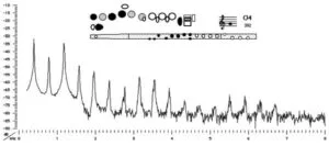
In order to create sound that resembled the sound of a flute, we first had to understand the spectrum of harmonics that a flute makes. The University of New South Wales published the following spectrum of a flute which we used as a starting point. An image of the spectrum is shown below in Figure 3.
DAC_data = (int)((0.5*cos_table[phase_accum_fm>>24])*(dac_data1+dac_data2+dac_data3+dac_data4));Changing the TFT Library
When we were originally determining which analog pins would be assigned to our microphone, we realized we didn’t have enough available analog pins. For that reason, we decided to edit the tft_master.h library and reassign the chip select line to be B7 instead of B1. We made this change because the chip select line does not have to be an analog pin. The changes to the library can be seen below:
#define _cs         LATBbits.LATB7
#define TRIS_cs     TRISBbits.TRISB7
#define _cs_high()  {LATBSET = 128;}
#define _cs_low()   {LATBCLR = 128;}
Hardware Design
The PIC32 controller from microchip is a low cost microcontroller controller with excellent features. The one such unique feature is Charge Time measurement Unit(CTMU). This peripheral provides a fixed current source internally on any of the GPIO pins.
This peripheral can be used to sense the touch of the human finger on any of the ADC pins of the microcontroller. Thus, it can also be used as a touch switch. The formula for capacitance is C=q/V where C is the capacitance, V is the voltage across the capacitor, and q is the charge which can also be denoted as the product of the current and time.
Hence the formula can also be demated as C=(I*t)/V
Using the CTMU, if a pin is provided with a fixed current for a fixed amount of tim, we get C as inversely proportional to V. This logic is used to measure the capacitance on an ADC pin which changes when the pin is touched and released.
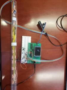
The capacitance switches were nothing but the wires connected to the Analog Multiplexers to measure the capacitance at each button. And the input of the multiplexer connected to the ADC pin of the microcontroller. Analog Multiplexers are single pole multiple throw switches and the state state of these switches are determined by the digital states of the select lines. In this case, there is single pole and 8 throws in the switch and this is controlled by three select lines. So if the select lines are 000, then the input is connected to the output 0, if the select lines are 111, then the input is connected to the output 7. In addition to these, there is also one chip select line which has an ability to turn off the entire chip so none of the outputs are connected to the input. This pin helps in multiplexing between different multiplexers.
In this project, 13 capacitive buttons were required, but the PIC32 does not provide that many ADC channels. With the help of multiplexers, all the buttons were connected using only one ADC channel and 5 other GPIO pins, which saved plenty of microcontroller pins.
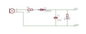
The microphone used in this project was from Adafruit which came in with ion board amplifier. The amplifier used a MAX4466 IC for amplification of the signal. The problem faced with his microphone was that the ADC readings obtained from this microphone were either in the range of 500s (when no wind is blown into it) or in the range of 900s (when the wind is being blown into it). Hence it was only used to control the octave being played by the flute.
Additionally, the signal that was obtained from the microphone was a sine wave. The ADC needed an absolute value in order to function properly. Hence, an extra circuit was designed to maintain the amplitude of the signal.
Results
The results of our multi-scale electronic flute met our expectations. The scales can be flexibly adjusted using two scale-selecting buttons. The CTMU can correspond to the corrected note that the user pressed and the response time is reasonable for a typical flute. The sound generated by our electronic flute is close to a typical bamboo flute sound. Also, our flute is designed considering the weight of a typical flute and the mounting locations of CTMU notes, The whole design is user friendly and can be easily operated by a flute player.
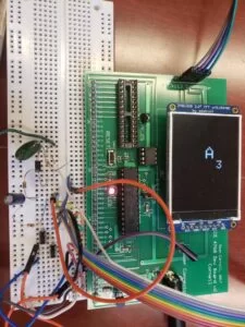
TFT display
CTMU and Microphone
The Microphone is used to detect the flow blowing from the user’s mouth and if it is energized, the sound will go to the high octave. The threshold for energizing the microphone was set by doing multiple tests and finalized to air blowing range suitable for the typical flute players. The threshold for CTMU detection was also determined by multiple testing corresponding to the capacitor charging time. The charging time is set to be two microseconds and the timer 2 for interrupt service routine is set to be 2000 samples per seconds. Considering the possibility that the charging time might be interrupted by interrupt service routine, the team enable and disable the timer 2 at the start and at the end of the CTMU charging time. Therefore, the response from CTMU notes is trustworthy to be a finger pressed if the ADC value is above the threshold.
Sound Synthesis
The sound generated by our electronic flute is close to a typical bamboo flute. The sound synthesis is implemented under several sound simulations in Matlab. The sound is manipulated by adding four other harmonics and envelope to maximum mimic the typical flute sound. The team conducted a research on close flute sound spectra and found the clarinet sound spectra figure from paper “Clarinet acoustics: introducing a compendium of impedance and sound spectra” written by Dickens P, France R, and eg. can proof our sound synthesis result is close to a flute sound and definately matched with the sound generated by a wind sound instrument.
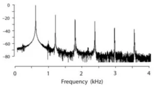
From two figures above, The first frequency is the main frequency, the rest of them are harmonics which are about two times, three times, and four times the main frequency. The amplitudes of harmonics are decreasing. The amplitude of the second harmonic is around -10 dB from the first frequency, and the third one is around -15 dB from the main frequency. The spectra from both figures are basically quite similar, though there are differences probably due to different scales the sound is synthesis.
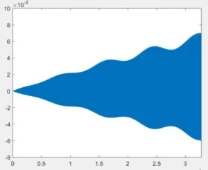
Apart from the frequency spectra, the team also added an envelope on the sound. By adding the envelope, the sound is closer to the bamboo flute which is our target. Since the air flow blowing from humans into the flute is less at first, gradually increase, and gradually decrease, the volume of the flute sound should also follow these criteria. The output of our envelope from the Matlab synthesis is shown below.
Conclusion and Further Improvements
Work Distribution
The team worked evenly for the final project. For the software part, the thread code for CTMU is mainly implemented by Parth and Trisha. The sound generation interrupt services routine is mainly implemented by Qing and Trisha. And three of us worked together on sound synthesis optimization. For hardware, Parth finished the basic flute implementation. Qing and Trisha worked on hardware testing. All in all, the group worked organized, efficient, and happy together.
Source: Electronic Flute
About The Author
Muhammad Bilal
I am a highly skilled and motivated individual with a Master's degree in Computer Science. I have extensive experience in technical writing and a deep understanding of SEO practices.