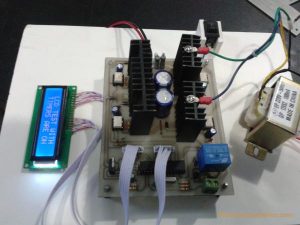
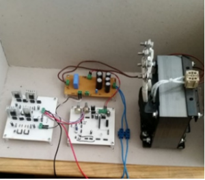
Summary of DsPIC33F microcontroller based pure sine wave inverter
This article discusses the design of a pure sine wave inverter based on the DsPIC33F microcontroller, which converts 12V DC from a battery into 220V, 50Hz AC using pulse width modulation (PWM). The inverter system has two parts: a control board generating PWM signals for MOSFET switching and a power board containing drivers and the H-bridge MOSFETs. This two-card design ensures protection of the control circuitry from high current damage during operation. The inverter is applicable in industrial uses like motor control and uninterruptible power supplies.
Parts used in the DsPIC33F microcontroller based pure sine wave inverter:
- DsPIC33F microcontroller
- MOSFETs (for H-bridge circuit)
- Driver circuits (for MOSFET control)
- Control board (PCB for PWM signal generation)
- Power board (PCB containing drivers and MOSFETs)
- 12V Battery (DC voltage source)
- Transformer (optional, to step up voltage to 220V)
In this post we will brielfy discuss DsPIC33F microcontroller based pure sine wave inverter. The majority of the technological devices used with the development of the technology use the network voltage (220V-50Hz).
Conversion must be done to obtain the mains voltage from the DC storage voltage sources. This conversion can be done by inverter. In this study, microprocessor-based inverter design is considered to transform the voltage from DC 12V battery to 50 Hz, 220V AC.

DsPIC33F microcontroller based pure sine wave inverter INTRODUCTION:
Inverters are used in many industrial applications nowadays and become an indispensable element of industrial and energy based systems. The inverters are used to convert the DC voltage that they receive from sources such as battery, solar panel, used as DC source to AC source. Inverters are used in many areas such as motor control, uninterruptible power
supplies, AC voltage sources, switched power supplies, induction heating.
DESIGNED INVERTER SYSTEM OVERVIEW:
Turning the low-voltage DC power to AC is completed in two steps. The low-voltage DC power is converted to a highvoltage DC source and converted to an AC waveform using pulse width modulation (PWM) of the high DC source. As a different alternative, the low-voltage DC power is first converted to AC and then a transformer is used to increase the
voltage to 220 volts.

The system consists of 2 cards including control and power card. The control board is the part where the PWM signals necessary for switching the MOSFETs in the H bridge circuit are generated via the microcontroller. The power card is the part where the drivers are sampled and where the MOSFETs are located. When the load is connected to the power card, the
system is designed as 2 different cards to prevent damage to the control card due to excessive current draw. Figure 5 shows the design of the control board.
Read More: To Download PDF Click Here
