


Summary of Driving a piezo speaker with a PIC using pic-microcontroller,
This article explains how to generate musical tones on a piezo speaker using a PIC microcontroller's Pulse Width Modulation (PWM) output. By adjusting the PWM period, specific frequencies for musical notes are produced, while the duty cycle controls volume. The project utilizes Timer 2 to manage frequencies between 2kHz and 10kHz, with a provided table mapping musical notes to timer scaling values and corresponding frequencies.Parts used in the Piezo Speaker Project:
- PIC Microcontroller
- Piezo Speaker (Parallax 900-00001)
- Timer 2
Overview
A Pulse Width Modulation (PWM) output from a PIC microcontroller can be used to play tones on a piezo speaker. With this, musical scales and simple songs can be played on the piezo speaker.
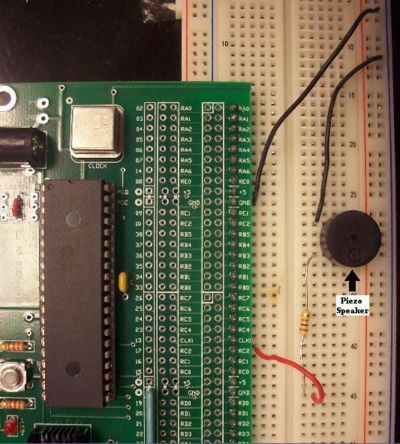
Piezoelectric speakers operate by the converse piezoelectric effect: when a voltage is applied across the terminals, the piezoelectric material in the speaker deflects in one direction. Applying an alternating voltage, such as a square wave, will cause the material to vibrate and create a sound. A constant voltage will not produce a sound.
PWM was used to provide the alternating voltage to drive the speaker (Parallax 900-00001). The period of the PWM determines the tone that will be played; the duty cycle changes the volume.
PWM Period
The frequency range of the speaker was limited by the timer used by the PIC to control PWM, which is Timer 2. First, we determined the PWM frequencies that we could use, which was from about 2kHz to 10kHz. Setting the lowest frequency as our first note (C), a set of timer scaling values that correspond to frequencies that would play the basic notes of an octave of the diatonic scale was found. The period of the PWM is given by the following equation:
Since the pulse width ratio would be at 100% when the duty cycle exceeds the period of PWM, the range of duty cycle values that will produce a sound on the piezo speaker depends on the period of the PWM pulses. Duty cycle values of 1~125 will allow us to play all the notes defined in our code. For very small and very high duty cycles, the volume is low.
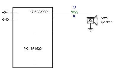
Frequency can be calculated by inverting the period. The table below displays the basic musical notes, their timer scaling value and the PWM frequencies in hertz.
| Note | Timer Scaling Value | Frequency (Hz) |
|---|---|---|
| C | 255 | 2441 |
| D | 227 | 2741 |
| E | 204 | 3048 |
| F | 191 | 3255 |
| G | 170 | 3654 |
| A | 153 | 4058 |
| B | 136 | 4562 |
| C2 | 127 | 4882 |
For more detail: Driving a piezo speaker with a PIC
Quick Solutions to Questions related to Piezo Speaker Project:
- How does a piezoelectric speaker produce sound?
A constant voltage will not produce a sound; applying an alternating voltage like a square wave causes the material to vibrate. - What determines the tone played on the speaker?
The period of the PWM determines the tone that will be played. - What changes the volume on the piezo speaker?
The duty cycle changes the volume. - Which timer is used to control the PWM?
Timer 2 is used by the PIC to control the PWM. - What frequency range was determined for the speaker?
The frequency range was limited to about 2kHz to 10kHz. - What duty cycle values allow playing all defined notes?
Duty cycle values of 1~125 will allow us to play all the notes defined in the code. - How is frequency calculated from the PWM period?
Frequency can be calculated by inverting the period. - What happens at very small or very high duty cycles?
For very small and very high duty cycles, the volume is low.
Related projects
Audio Spectrum Analyzer
We developed an audio spectrum analyzer as our final project for ECE 4760. This analyzer presented a histogram-style representation of audio signals....
Audio, Sound & Radio · PIC12F675Audio CRO using PIC12F675 Microcontroller
This project is a miniature Audio CRO. For those not familiar with the abbreviation "CRO," it means "Cathode Ray Oscilloscope" and this...
Audio, Sound & RadioBuild a musical EKG with the Freescale FRDM-KL05
Short Introduction: I have been following the Battle of the DreamBoards Championship with interest and I enjoyed the variation of functionality features...
Audio, Sound & RadioPIC MicroController Volume Adjuster Program(Proteus 8 Stimulation)
Hello everyone, The important aspect of every learning is to induce curiosity and doing something meaningful to satisfy that.With the help of...
Audio, Sound & RadioWireless Radio Frequency Module Using PIC Microcontroller
It's a Microcontroller Based DIY Electronics Project. Named Wireless RF Module Using PIC Microcontroller. The RF module is a small electronic circuit...
Audio, Sound & Radio · PIC16F676Shrieker using PIC16F676 Microcontroller
Recently a cell phone ring tone was in the news - it's 17,000 Hertz and meant to be heard by teenagers, but...

Ibrar Ayyub
I am an experienced technical writer holding a Master's degree in computer science from BZU Multan, Pakistan University. With a background spanning various industries, particularly in home automation and engineering, I have honed my skills in crafting clear and concise content. Proficient in leveraging infographics and diagrams, I strive to simplify complex concepts for readers. My strength lies in thorough...