Summary of DMX-512 to Serial Adapter
This article details a DMX-512 to Serial Adapter project that converts DMX signals into TTL serial data for microcontrollers like Arduino or PIC. Using two enhanced Mid Range PICs (12F1822 and 16F1828), the device reads DMX addresses via DIP switches, processes channel data at 250k baud internally, and transmits it externally at 57200 or 19200 baud upon request. It supports parallel DMX pass-through, signal re-transmission, and custom universe generation, featuring configurable jumpers for various operational modes.
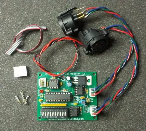
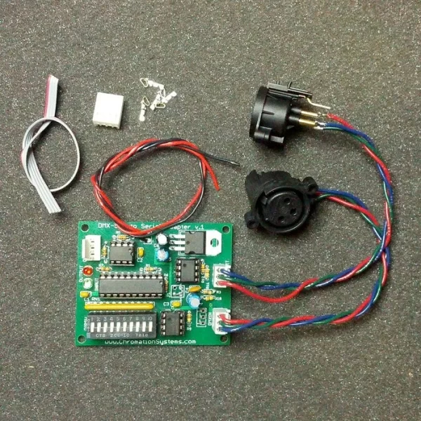
Parts used in the DMX-512 to Serial Adapter:
- Printed Circuit Board
- PIC12F1828 DIP (Programmed)
- PIC12F1822 DIP (Programmed)
- SN75174 RS-485 Transceiver
- DIP Sockets
- 7805 Voltage Regulator
- Male XLR Panel Mount Connector
- Female XLR Panel Mount Connector
- 10 Position DIP Switch
- LEDs
- Resistor Network
- Various Resistors
- Twisted Wire
- Molex Headers and Housings
- Crimps
- Disc Capacitors
- Electrolytic Capacitors
This device reads a DMX-512 signal and grabs a variable amount of channel data values and sends them at 57200 or 19200 baud to an external device, such as a 24 Channel High Current LED Controller, when a new data packet is requested. This allows any microcontroller(PIC, Arduino, ATMel, ect.) with TTL serial communication to accept DMX-512 data without the overhead of decoding the DMX signal and grabbing the necessary data values.
This is done utilizing two enhanced Mid Range PICs, 12F1822 and 16F1828. The 16F1828 reads the DIP switch to get the DMX address, reads the DMX-512 signal and saves the desired channel data to RAM. It signals to the 12F1822 to reset its buffer then sends the DMX channel data to the 12F1822 at 250k baud(DMX speed). The 12F1822 accepts the data from the 16F1828 and waits for the external device to reset its buffer and signal a request for a new data packet. When the 12F1822 recieves a data request it switches from 250k baud to 57600(default,19200 firmware available) and sends the DMX data values as standard TTL serial bytes to the external device. The external device then does what it needs with the data, and requests a new packet when it is ready.
This device has the option to either have the DMX In and Out in parallel(industry standard) or it can be setup to re-transmit the DMX signal unaltered and boosted.(shown in this Instructable) In addition the hardware circuitry and software functions are included to transmit a custom or altered DMX universe, independent from the receiving DMX universe.
For Datasheet, Kits, Links, and Downloads Please Visit the DMX to Serial Adapter Webpage
Attachments
Step 1: Parts and Tools
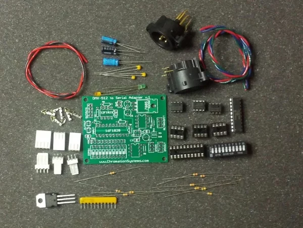
Parts:
- Printed Circuit Board – Files included in the Project ZIP
- PIC12F1828, DIP – Buy One Programmed
- PIC12F1822, DIP – Buy One Programmed
- 2x SN75174, DIP, RS-485 Transceiver
- 3x 8-pin DIP Sockets
- 1x 20-pin DIP socket
- 7805 Voltage Regulator, TO-220
- Male XLR, Panel Mount
- Female XLR, Panel Mount
- 10 position DIP switch, CT20818-ND on Digikey
- 2x LEDs, 2 different colors
- 10 position 10k resistor network, 11-pin SIP package, 11X-1-103LF
- 4x 100kohm 1/6w resistor, DMX pull up/down
- 2x 10kohm 1/6w resistor
- 1x 100 ohm 1/6w resistor, Break Resistor
- 1x 10 ohm 1/6w resistor
- 1x 120 ohm, 1/6w resistor, DMX Termination
- 12″ 3-strand twisted wire for XLRs
- 8″ 2-strand wire for power connection
- 2x 3-pin Polarized Header, Molex 22-27-2031
- 2x 3-pin matching housing, Molex 22-01-2035
- 1x 4-pin Polarized Header, Molex 22-27-2041
- 1x 4-pin matching housing, Molex 22-01-2045
- 12x Crimps for header/housings, 10 required, 2 extra, Molex 08-50-0032
- 3x 0.1uF disc capacitor
- 1x 0.01uF disc capacitor
- 2x 1uF, 6v or higher, electrolytic capacitor
- 1x 10uF, 16v or higher, electrolytic capacitor
- LED, 3mm, Color 1
- LED, 3mm, Color 2
Tools:
- Soldering Iron and Solder
- Diaginol Cutter
- Needle Nose
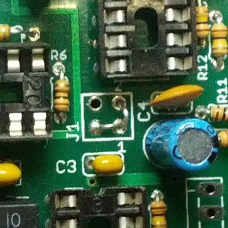
Step 2: Resistors, Disc Capacitors, & Sockets
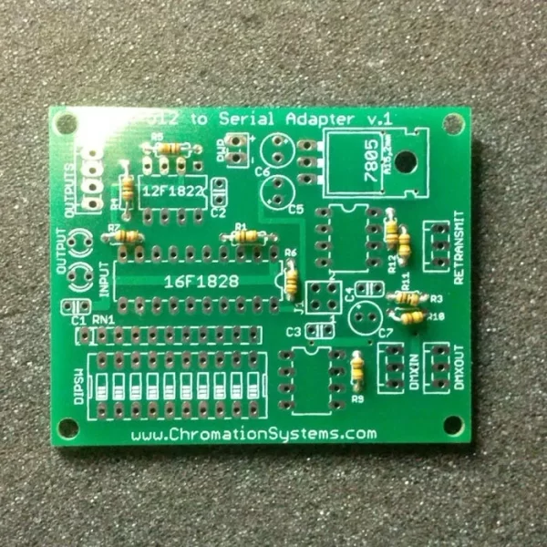
Resistors:
- R1 – 10kohm MCLR Pull-up
- R3 – 10 ohm
- R4 & R7 – 1kohm, LED indicator resistors
- R5 – 10kohm MCLR Pull-up
- R6 – 100 ohm, DMX Transmit Break Resistor
- R9, R10, R11, R12 – 100kohm, DMX Pull-up/Pull-Down
Sockets:
- Line up the notch on the socket to the notch on the top-side illustration
- Carefully ensure all the pins are in the holes and press the socket in
- Repeat with 3x 8-pin sockets and the single 20-pin socket
Capacitors:
- C1, C2, C3 are 0.1uF, marked 104
- C4 is 0.01uF, marked 103
Resistor Network: This pulls up the DIP switch input ports, Labeled RN1
- Line the dot on the SIP package up with the square on the far end of the resistor network’s top-side illustration(under C1 label)
- Insert and solder in
Step 3: Stuff
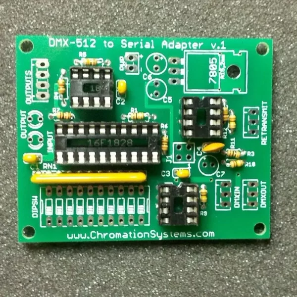
Eletrolytic Capacitors: These are polarized, the stripe down the side indicates the negative lead.
- C6 is a 10uF
- C5 & C7 is 1uF
LEDs: The flat side of the case and/or the short lead indicates the negative lead.
- Install the LEDs, ensuring they are in correctly, negative lead go in the holes closest to the edge of the PCB.
DIP Switch: This can either go in from the top which is standard, or it can be attached from the bottom which may make mounting in a case easier.
- Insert the DIP switch like seen in the image with the numbers closer to the 16F1828
Headers/Housings: These are optional, but make connection easier. Please see This Webpage for details on attaching crimps to the wires
- Insert the headers into their locations as pictured, the ramps don’t have to face outward.
7805: This is optional depending on the input voltage.
- If the input voltage is 5v, exclude the 7805 and jump the two outer holes with a jumper wire.
- If the voltage is greater than 7v install the 7805 as pictured.
Step 4: Function Select Jumpers & XLRs
This device can be used for purposes other than it’s designed use of converting DMX-512 signal to TTL serial for use with microcontrollers. The jumpers can be configured for different uses.
Retransmit: Incoming DMX data signal is read and sent(cloned) without modification. The DMX in connector connected to DMXIN, the DMX out(female) connected to RETRANSMIT. Must install the 120 ohm termination resistor on DMX In.
Passive Reception: DMX Data is only read, DMX input and output connectors are in parallel. No 120ohm termination resistor.
Normal Reception, Firmware Retransmit: DMX input is read, a firmware generated DMX universe is transmitted, firmware can be written to convert, reorganize, or perform mathematical functions on incoming data and transmit the edited universe, or a generated universe. Must install the 120 ohm termination resistor on DMX In.
Firmware Swappable: Not implemented as it was not considered during design. But a NPN transistor(2n3904 or similar) can be used to switch between Retansmit and Normal Reception, Firmware Retransmit modes during runtime. Must install the 120 ohm termination resistor on DMX In.
XLRs: A Male XLR is used for DMX input and a female XLR for DMX output. They are both pinned out the same.
- Cut some twisted, 3-strand wire to length
- Strip the ends and solder as follows
- XLR 1 is the blue wire
- XLR 2 is the green wire
- XLR 3 is the red wire
- Attach crimps and housing if desired.
- If configuring for a re-transmit, the 120 ohm termination resistor should be installed on the DMX In Connector, XLR Male, across pins 1 and 3. Either do this on the XLR, or it can be done on the extra DMX In 3-pin header position,
Do not forgot to install the 120 ohm termination resistor if required, either solder it between pins 2 and 3 on the connector, or solder the resistor to the PCB through the unused DMXIN header or from the bottom of the PCB.
Step 5: Firmware
This device is partly for communication with compatible controllers and also as a developer DMX platform.
Compatible Chromation Systems LED Controllers can be used or a simple communication protocol could be written to work with an Arduino or any other type of microcontroller system.
The source code and MPLAB project is included with purchase of a kit, and is available for download for a small fee. Written in Assembly for maximum efficiency. Full image preview available.
Sending a pulse of at least 1uS to Pin 1 of the Output Header, will signal to the 12F1822 that the external device is ready for a new data packet and has reset it’s buffer, it then sends default of 24 bytes(firmware can be modified for more or less bytes) out at 56,700 baud(also could be modified) over it’s TTL UART once it has collected the data packet from the 16F1828.
The current version of the firmware will attempt to transmit a firmware generated universe on DMXout if DIP Switch 10 is On, leave DIP 10 off if using adapter normally.
DMX Communication: Compatible Chromation Systems LED Controllers can be used or a simple communication protocol could be written to work with an Arduino or any other type of microcontroller system.
How to Communicate: Sending a pulse of at least 1uS to Pin 4 of the Output Header, will signal to the 12F1822 that the external device is ready for a new data packet and has reset it’s buffer, it then sends default of 24 bytes(firmware can be modified for more or less bytes) out at 56,700 baud over it’s TTL USART once it has collected the data packet from the 16F1828
SPI:
The 12F1822 could be configured to interface with the external device over a SPI interface, but the firmware is currently not available, but could be written.
Step 6: All Done
This device currently works with the 24 Channel High Current LED Controller using a special Firmware, which is available for download, Find it Here, and soon will be compatible with ColorMotion v2 firmwares.
This RGB LED panel was built utilizing a 24 Channel High Current LED Controller and a DMX to Serial Adapter. It is fully DMX controllable in addition to ColorMotion standalone functionality.
Please check my Instructables Profile and my website www.ChromationSystems.com for more projects.
Source: DMX-512 to Serial Adapter
- How does the device handle DMX signal conversion?
The device uses two PIC microcontrollers to read DMX-512 signals and send variable channel data as standard TTL serial bytes at 57200 or 19200 baud. - What is the function of the 16F1828 microcontroller?
The 16F1828 reads the DIP switch for the DMX address, receives the DMX signal, saves data to RAM, and sends it to the second chip at 250k baud. - Can the external transmission speed be changed?
Yes, the default speed is 57200 baud, but firmware is available to change this to 19200 baud. - How do I configure the device for re-transmit mode?
To re-transmit unaltered DMX data, connect DMX In to DMXIN and the female output to RETRANSMIT while installing a 120 ohm termination resistor on the DMX In connector. - What happens if DIP Switch 10 is turned on?
If DIP Switch 10 is On, the firmware attempts to transmit a generated DMX universe on the DMXout rather than passing through incoming data. - How does an external device request new data packets?
An external device must send a pulse of at least 1uS to Pin 1 or Pin 4 of the Output Header to signal readiness and reset the buffer. - Is SPI interface support currently available?
No, although the hardware could be configured for SPI, the firmware for this interface is not currently available. - Which controllers are compatible with this adapter?
The device works with 24 Channel High Current LED Controllers using special firmware and will soon be compatible with ColorMotion v2 firmwares.