Summary of DIY 32ch FPV 5.8ghz LCD
This DIY project involves building a custom 32-channel FPV 5.8GHz LCD monitor compatible with all transmitters by repurposing an existing LCD screen and integrating it with an RX5808 Pro receiver board. The builder disassembled the original unit, removed unnecessary buttons, and installed new electronics including a charging module, a 12V booster, and the receiver PCB to create a functional, self-powered display system.
Parts used in the DIY 32ch FPV 5.8ghz LCD:
- Existing LCD screen
- RX5808 PCB (Receiver Board)
- Charging module (Blue PCB)
- 12v Booster module (Green PCB)
- Switch
- Kapton tape
- Hot glue
- Pcb protect spray or stickers
If you’re like me, you don like buying stuff that’s ready-to-go, but rather build one yourself. We usually spend more money, but it’s way more satisfying I really didn’t want to buy an overly expensive 32ch FPV LCD receiver, so I made my own DIY 32ch FPV 5.8ghz LCD, that is compatible with EVERY transmitter on the market now.First, crack open that LCD, and look what’s inside. I desoldered the wires, and took note on how they were connected. The LCD operates on around 12v and my RX5808 pcb has the voltage regulator on it, so you can power it from the same 12v.
Although this LCD has 2 input channels, I only chose to use one. You can solder a wire on that second pad and leave it hanging out of course I removed the three LCD buttons, so there is no way of switching between inputs. Take note that the LCD defaults to the active source on startup.
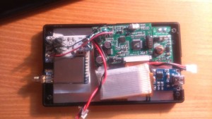
Next thing I did, was to mock up all the guts that Im going to put inside the LCD.
The whole electronic installation is really straight-forward. The blue pcb is the Charging module, small Green one is 12v booster. Connect the battery to the charging module, also connect the same wires to Booster module. Connect Booster output to LCD board and FPV board. Throw in a switch between charger and booster and voila! we’re done. Not hard now, was it?
Fix everything inside with kapton tape and hot glue. The back of the LCD panel is all metal, so you might want to put some stickers on it, or spray it with pcb protect spray. Be creative. B. E. Creative. You can see the DirtyPCB shipping information sticker I used
The neat thing about RX5808 pro is that it has spectrum scanner, and RSSI calibration (btw, that switch on the fpv board? switch between config and camera screen).
For more detail: DIY 32ch FPV 5.8ghz LCD
- How can I power this custom LCD?
The LCD operates on around 12v and is powered via the RX5808 PCB voltage regulator connected to a battery through a charging module. - Can this setup work with different transmitters?
Yes, the project creates a DIY 32ch FPV 5.8ghz LCD that is compatible with every transmitter on the market. - What happens if I use the second input channel?
You can solder a wire to the second pad and leave it hanging, though the author only chose to use one channel. - Does the LCD switch inputs automatically on startup?
Yes, the LCD defaults to the active source on startup since the three original buttons were removed. - What components are needed for the electronic installation?
The installation requires a blue charging module, a small green 12v booster, and connecting wires between the battery, modules, and boards. - How do I secure the internal components?
You should fix everything inside with kapton tape and hot glue. - Is there a way to calibrate the signal strength?
Yes, the RX5808 pro board features RSSI calibration capabilities. - How do I switch between config and camera screens?
There is a specific switch on the FPV board that allows you to switch between config and camera screen modes.