Summary of Displaying Scrolling(Moving) text on 16×2 lcd Using Pic16f877 and Pic18f452 Microcontroller
Displaying moving text on LCDs (commonly 16×2) is implemented using PIC microcontrollers by sending LCD commands and data via port pins and using delays to control scroll speed. The project uses PIC16F877 or PIC18F452, connects LCD data lines to PORTB and control lines to PORTD, initializes the LCD, writes a text string, and issues the LCD shift command (0x18) to scroll characters left when they reach the end. Code is provided in C for Hi-Tech C/MPLAB and includes circuit details, timing, and configuration for reliable scrolling.
Parts used in the Displaying Scrolling(Moving) text on 16×2 lcd Using Pic16f877 and Pic18f452 Microcontroller:
- PIC16F877 microcontroller
- PIC18F452 microcontroller (alternative)
- 16×2 LCD module (Hitachi compatible)
- Potentiometer / variable resistor (for LCD contrast)
- 20 MHz crystal (for PIC16F877)
- Two 33 pF capacitors (for crystal)
- Power supply (5 V)
- Connection wires and breadboard or PCB
- MPLAB IDE and Hi-Tech C compiler (for compiling C code)
- Proteus (for simulation)
Scrolling/Moving text on lcd with pic microcontroller – Project requirements
- Pic 16f877 microcontroller
- 16×2 lcd (I am using.)
- Potentiometer/variable resistor (To set lcd contrast)
- crystal(20 MHz)
- Power supply
If you are newbie and don’t know much about 16×2 lcd working and pin out just go through this simple tutorial. It will explain you about all the pins and functions of 16×2 lcd.
16×2 lcd pinout and working.
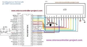
Pic microcontroller scrolling text – Project circuit
Pic microcontroller moving text on lcd – Project code
After the header files now its time to define our functions. First i defined delay function which is used to generate some delay in program execution.Next comes lcd command function.
lcdcmd() function is sending commands to 16×2 lcd. For sending commands first put your command on port-b then select register(to select command register make rs=0). After selecting the command register select which operation you want to perform read or write(for read make rw=1 and write make rw=0). Finally to display character on 16×2 lcd screen give strobe to write command present on data pins of 16×2 lcd. Just make en high(en=1) and after few micro seconds bring it back to low (en=0).
display() functions works in the same way as lcdcmd but with little difference that except command it is writing data on lcd and you just need to select the data register to write data(rs=1 takes you to lcd data register).
lcdint() function is initializing our lcd and pic microcontroller ports. TRISB=0x00 declares pic microcontroller port-b as output port. TRISD5=0,TRISD6=0 & TRISD7=0 are making individual pins of port-d as output. Rest of the commands are initializing our 16×2 lcd. If you want to know about the functions of the commands just go through the tutorial(Link is given at the top after first paragraph).
In the main function i am displaying text on 16×2 lcd. I start displaying text from first coulomb of row 1 and when my text reaches at the end of the row 1 i start scrolling the text to the left.The statement if(i>=14){lcdcmd(0x18);} is performing this function. When my text reaches to last coulomb of 16×2 lcd which is 15 i start scrolling it to left. The command/statement lcdcmd(0x18) scrolls the text on 16×2 lcd using pic microcontroller.
I recommend you to please go through the tutorial 16×2 lcd pinout and working if you don’t understand commands and their working.
| #include <htc.h> | |
| #define _XTAL_FREQ 20000000 | |
| char text[]={“microcontroller-project.com “}; | |
| void delay(unsigned int time) //Time delay function | |
| { | |
| unsigned int i,j; | |
| for(i=0;i< time;i++) | |
| for(j=0;j< 5;j++); | |
| } | |
| //Function for sending values to the command register of LCD | |
| void lcdcmd(unsigned char value) | |
| { | |
| PORTB=value; | |
| RD6= 0; //register select-rs | |
| RD5 = 0; //read-write-rw | |
| RD7 = 1; //enable-e | |
| delay(50); | |
| RD7=0; //enable-e | |
| delay(50); | |
| } | |
| //Function for sending values to the data register of LCD | |
| void display(unsigned char value) | |
| { | |
| PORTB=value; | |
| RD6= 1; //register select-rs | |
| RD5= 0; //read-write-rd | |
| RD7= 1; //enable-e | |
| delay(500); | |
| RD7=0; //enable-e | |
| delay(50); | |
| } | |
| //function to initialize the registers and pins of LCD | |
| //always use with every lcd of hitachi | |
| void lcdint(void) | |
| { | |
| TRISB=0x00; //PortB is used as output port | |
| TRISD5=0; | |
| TRISD6=0; | |
| TRISD7=0; | |
| delay(15000);display(0x30);delay(4500);display(0x30);delay(300);display(0x30);delay(650); | |
| lcdcmd(0x38); //Character font made is 5×7 matrix | |
| delay(50); | |
| lcdcmd(0x0C); | |
| delay(50); | |
| lcdcmd(0x01); | |
| delay(50); | |
| lcdcmd(0x06); | |
| delay(50); | |
| lcdcmd(0x80); //Selects 16×2 lcd coulomb 1 row 1 | |
| delay(50); | |
| } | |
| void main() | |
| { | |
| unsigned int i; | |
| lcdint(); | |
| while(1){ | |
| lcdcmd(0x80); | |
| lcdcmd(0x01); | |
| i=0; | |
| while(text[i]!=‘\0‘){ | |
| display(text[i]); | |
| delay(2000); | |
| if(i>=14) | |
| {lcdcmd(0x18);} | |
| delay(3000); | |
| i++; | |
| } | |
| lcdcmd(0x01); | |
| delay(5000); | |
| } | |
| } |
Watch the Project video Here…..
https://www.facebook.com/electronicsgru/videos/701588303304145/?t=0
Moving Scrolling Text on lcd using Pic18f452 Microcontroller
In simulation both pic microcontroller codes hex files are given. You can verify both the codes working accurately according to our requirements by running simulation on both the codes hex files separately.
| #include <p18f452.h> | |
| //#define _XTAL_FREQ 4000000 //Frequency of Oscillator 4MHz | |
| //_CONFIG_DECL(0x21,0x01,0x00,0x01,0x10,0x0F,0x30,0x0F,0xE0,0x0F,0xF0); | |
| #pragma config OSC = XT | |
| #pragma config OSCS = OFF | |
| #pragma config PWRT = OFF | |
| #pragma config BOR = OFF | |
| #pragma config BORV = 27 | |
| #pragma config WDT = OFF | |
| #pragma config WDTPS = 1 | |
| #pragma config CCP2MUX = ON | |
| #pragma config STVR = OFF | |
| #pragma config LVP = ON | |
| #pragma config DEBUG = OFF | |
| #pragma config CP0 = OFF | |
| #pragma config CP1 = OFF | |
| #pragma config CP2 = OFF | |
| #pragma config CP3 = OFF | |
| #pragma config CPB = OFF | |
| #pragma config CPD = OFF | |
| #pragma config WRT0 = OFF | |
| #pragma config WRT1 = OFF | |
| #pragma config WRT2 = OFF | |
| #pragma config WRT3 = OFF | |
| #pragma config WRTB = OFF | |
| #pragma config WRTC = OFF | |
| #pragma config WRTD = OFF | |
| #pragma config EBTR0 = OFF | |
| #pragma config EBTR1 = OFF | |
| #pragma config EBTR2 = OFF | |
| #pragma config EBTR3 = OFF | |
| #pragma config EBTRB = OFF | |
| void delay(unsigned int time) //Time delay function | |
| { | |
| unsigned int i=0,j=0; | |
| for(i=0;i< time;i++); | |
| //for(j=0;j< 2;j++); | |
| } | |
| //Function for sending values to the command register of LCD | |
| void lcdcmd(unsigned char value) | |
| { | |
| PORTB=value; | |
| PORTDbits.RD6= 0; //register select-rs | |
| PORTDbits.RD5 = 0; //read-write-rd | |
| PORTDbits.RD7 = 1; //enable-e | |
| delay(50); | |
| PORTDbits.RD7=0; //enable-e | |
| delay(50); | |
| } | |
| //Function for sending values to the data register of LCD | |
| void display(unsigned char value) | |
| { | |
| PORTB=value; | |
| PORTDbits.RD6= 1; //register select-rs | |
| PORTDbits.RD5= 0; //read-write-rd | |
| PORTDbits.RD7= 1; //enable-e | |
| delay(50); | |
| PORTDbits.RD7=0; //enable-e | |
| delay(50); | |
| } | |
| //function to initialize the registers and pins of LCD | |
| //always use with every lcd of hitachi | |
| void lcdint(void) | |
| { | |
| TRISB=0x00; //Port B is used as output port | |
| TRISD=0x05; | |
| delay(15000); | |
| display(0x30); | |
| delay(4500); | |
| display(0x30); | |
| delay(300); | |
| display(0x30); | |
| delay(650); | |
| lcdcmd(0x38); //5×7 Font text will be displayed on lcd | |
| delay(50); | |
| lcdcmd(0x0C); //Display on Cursor off | |
| delay(50); | |
| lcdcmd(0x01); //Clear LCD (DDRAM) | |
| delay(50); | |
| lcdcmd(0x06); //Entry Mode | |
| delay(50); | |
| lcdcmd(0x80); //Put Cursor at first line first character space | |
| delay(50); | |
| } | |
| void main() | |
| { | |
| unsigned int i=0; | |
| char text[]={“I Love Pakistan!!!!!“}; | |
| lcdint(); //Initialize lcd | |
| while(1){ | |
| lcdcmd(0x80); //Place cursor on first line first character space of lcd | |
| i=0; | |
| if(PORTDbits.RD0==0){ | |
| PORTDbits.RD1=1; | |
| for(i=0;i<1000;i++); | |
| PORTDbits.RD1=0; | |
| for(i=0;i<1000;i++); | |
| } | |
| if(PORTDbits.RD2==0){ | |
| while(text[i]!=‘\0‘){ //Displaying Text on LCD | |
| display(text[i]); | |
| delay(200); | |
| if(i>=14) | |
| { | |
| lcdcmd(0x18); //Moving Display left | |
| } | |
| delay(300); | |
| i++; | |
| } | |
| } | |
| } | |
| } |
- How is the LCD data connected to the PIC microcontroller?
Data pins of the 16×2 LCD are directly connected to PORTB of the PIC microcontroller. - Which PIC pins are used for RS, RW, and EN on the LCD?
RS is connected to PORTD pin 6, RW to PORTD pin 5, and EN to PORTD pin 7 for the PIC16F877; PORTDbits.RD6, RD5, RD7 are used similarly for PIC18F452. - What command is used to scroll the display left?
The lcdcmd(0x18) command is used to scroll the text to the left. - How is the LCD initialized in the code?
The lcdint() function configures TRISB and TRISD pins, sends initialization sequences (0x30 multiple times), and issues commands like 0x38, 0x0C, 0x01, 0x06, and 0x80. - Can the same technique be used with PIC18F452?
Yes, the technique is the same; only code syntax and register names differ, and an example PIC18F452 code is provided. - What determines the scrolling speed and stability?
Crystal frequency and delay values in the code determine speed and stability; lowering frequency or increasing delays slows the scrolling. - How is contrast adjusted for the LCD?
Contrast is set by rotating the potentiometer/variable resistor connected to the LCD contrast pin. - Do both codes require changes in the circuit diagram?
No, both PIC16F877 and PIC18F452 codes use the same circuit connections and do not require changing the circuit diagram. - What development tools and simulation software are used?
MPLAB IDE with Hi-Tech C compiler is used for code; Proteus (Proteaus 8.0) is used for simulation. - What text was used as an example to scroll on the LCD?
The example text string is microcontroller-project.com for the PIC16F877 code and I Love Pakistan!!!!! for the PIC18F452 example.