
In this article you will learn, Digital Thermometer using pic microcontroller and MCP9700:
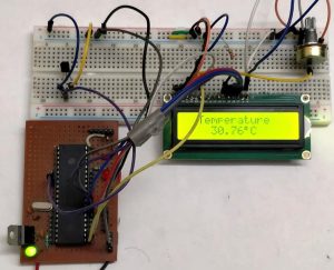
In this tutorial, we are making a Digital Thermometer using PIC microcontroller and LM35 Temperature Sensor. In this project, we will sense the temperature using LM35 and display it on 16×2 LCD. LM35 Temperature Sensor is accurate and cheaper and doesn’t require any external calibration. The output voltage is proportional to Celsius temperature scale and changes by 10mV per °C.
Material Required
- PicKit 3
- LM35 Temperature Sensor
- 16*2 LCD
- PIC16F877A IC
- 40 – Pin IC holder
- Perf board
- 20 MHz Crystal OSC
- Female and Male Bergstick pins
- 33pf Capacitor – 2Nos, 100uf and 10uf cap.
- 680 ohm, 220 ohm, 10K and 560ohm Resistor
- Potentiometer 10k
- LED of any color
- 1 Soldering kit
- IC 7805
- 12V Adapter
- Connecting wires
- Breadboard
LM35 Temperature Sensor:
LM35 temperature sensor has zero offset voltage, which means at 0°C the output will be 0V. The maximum voltage it can handle is 1.5V which means it can be able to sense a maximum temperature of 150°C (1.5V / 10mV).
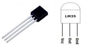
| Pin No | Function | Name |
| 1 | Supply voltage; 5V (+35V to -2V) | Vcc |
| 2 | Output voltage (+6V to -1V) | Output |
| 3 | Ground (0V) | Ground |
We have already used LM35 with many other microcontrollers to measure the temperature:
- Digital Thermometer using LM35 and 8051 Microcontroller
- Temperature Measurement using LM35 and AVR Microcontroller
- Digital Thermometer using Arduino and LM35 Temperature Sensor
- Room Temperature Measurement with Raspberry Pi
As we already told that LM35 gives analog output, so first we need to read that analog values using PIC Microcontroller and then we will convert them into digital values using ADC (Analog to Digital Conversion). So we will learn ADC in PIC Microcontroller before going any further.
ADC in PIC Microcontroller PIC16F877A:
There are many types of ADC available and each one has its own speed and resolution. The most common types of ADCs are flash, successive approximation, and sigma-delta. The type of ADC used in PIC16F877A is called as the Successive approximation ADC or SAR in short. So let’s learn a bit about SAR ADC before we start using it.
Successive Approximation ADC: The SAR ADC works with the help of a comparator and some logic conversations. This type of ADC uses a reference voltage (which is variable) and compares the input voltage with the reference voltage using a comparator and difference, which will be a digital output, is saved from the Most significant bit (MSB). The speed of the comparison depends on the Clock frequency (Fosc) on which the PIC is operating.
For more detail: digital thermometer using pic microcontroller and MCP9700
About The Author
Ibrar Ayyub
I am an experienced technical writer holding a Master's degree in computer science from BZU Multan, Pakistan University. With a background spanning various industries, particularly in home automation and engineering, I have honed my skills in crafting clear and concise content. Proficient in leveraging infographics and diagrams, I strive to simplify complex concepts for readers. My strength lies in thorough research and presenting information in a structured and logical format.
Follow Us:LinkedinTwitter