Summary of Measure small currents without adding resistive insertion loss
### Summary This article describes a circuit design for measuring small currents without introducing resistive insertion loss. Unlike traditional methods that use probing resistors or sink current to ground, this configuration uses two operational amplifiers (IC1 and IC2). The circuit sinks incoming current through one op amp while sourcing an equal outgoing current back to the test circuit via the other. By maintaining equal voltages at the inputs and using matched resistors (R1=R2), the system ensures the measured current flows with virtually no resistance added to the circuit under test.
Parts used in Current Measurement Circuit:
- Probing resistor (RP)
- Differential amplifier IC1
- Operational amplifier (Op Amp) for current-to-voltage conversion
- Feedback resistor
- Input current path
- Sensing node
- Resistor R1
- Resistor R2
- Resistor R3
- Resistor R4
- Op amp IC1
- Op amp IC2
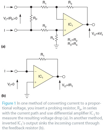 In most cases, you measure current by converting it into a proportional voltage and then measuring the voltage. Figure 1 shows two typical methods of making the conversion. In one method, you insert a probing resistor, RP, in series with the current path and use differential amplifier IC1 to measure the resulting voltage drop (Figure 1a). A second method is a widely known operational amplifier current-to-voltage converter in which inverted IC1’s output sinks the incoming current through the feedback resistor (Figure 1b).
In the first method, the same current that flows into one node flows from the second node, but a significant voltage drop occurs across probing resistor RP. In the second method, the voltage drop is on the order of tens of microvolts to millivolts, depending on IC1’s quality, but the measured current flows only into the sensing node with no return to the circuit. You can measure only currents flowing to ground.
The circuit in Figure 2 operates in a somewhat similar manner to the one in Figure 1b in that an op amp’s output sinks the incoming measured current. However, the other op amp’s output sources an equal outgoing current back to the circuit under test.
In Figure 2, input current I flows through R1 into the output of IC2, which reduces its voltage by the amount of IR1 relative to the input node. That voltage equals the voltage mean of the op amp’s outputs, which R3 and R4 set at the op amp’s inverting inputs. Consequently, the output of IC1 must rise to a voltage of IR2 relative to the inverting inputs and the equal-voltage noninverting input node of IC2. IC1 sources this current, which returns through R2 to the circuit under test. R1=R2, so the output current is the same as the input current. Because the op amp’s outputs maintain their inputs at equal voltages, the circuit under test has virtually no resistance.
- How do you typically measure current?
You measure current by converting it into a proportional voltage and then measuring that voltage. - What happens in the first method of current conversion?
A significant voltage drop occurs across the probing resistor RP when inserting it in series with the current path. - Can you measure only currents flowing to ground in the second method?
Yes, in the second method where the op amp output sinks incoming current, you can measure only currents flowing to ground. - Does the circuit in Figure 2 source current back to the circuit under test?
Yes, the output of the second op amp sources an equal outgoing current back to the circuit under test. - Why does the circuit under test have virtually no resistance?
The op amp outputs maintain their inputs at equal voltages, preventing resistive insertion loss. - What is the relationship between R1 and R2 in this circuit?
R1 equals R2, ensuring the output current is the same as the input current. - How does the voltage of IC1 change relative to the inputs?
The output of IC1 must rise to a voltage of IR2 relative to the inverting inputs and the noninverting input node of IC2. - What sets the voltage mean of the op amp outputs?
Resistors R3 and R4 set the voltage mean at the op amp's inverting inputs.