Summary of Digital Speedometer and Odometer Circuit using PIC Microcontroller
This project builds a digital speedometer and odometer using a PIC16F877A microcontroller, a Hall effect sensor with a magnet to detect rotations, and a 16x2 LCD to display speed and distance. It uses interrupts and timers to count pulses and compute RPM, speed, and distance. Simulation in Proteus verifies LCD behavior; during simulation the Hall sensor may be replaced by a logic switch to trigger interrupts and observe updates.
Parts used in the Digital Speedometer and Odometer Circuit using PIC Microcontroller:
- PIC16F877A microcontroller
- Hall effect sensor
- Magnet (mounted on rotating object)
- 16x2 LCD display
- Proteus software for simulation
- Logic state device/button (for simulation trigger)
- Supporting passive components (wires, resistors, power supply)
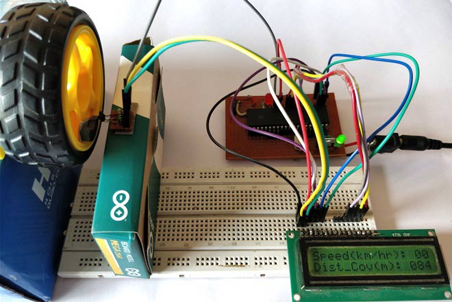
Measuring the speed/rpm of a Vehicle or a motor has always been a fascinating project for us to try. So, in this project we are going to build one using the Industrial ready PIC microcontrollers. We will use a piece of magnet and a Hall Sensor to measure the speed. There are other ways/sensors to measure the speed but, using a hall sensor is cheap and also can be used on any type of motor/Vehicle. By doing this project we will also enhance our skills in learning PIC16F877A since the project involves the use of Interrupts and Timers. At, the end of this project you will be able to calculate the speed and distances covered by any rotating object and display them on a 16×2 LCD screen. Lets start with this Digital Speedometer and Odometer Circuit with PIC
Simulation:
The Simulation for this project is done using Proteus. Since the project involves moving objects it is not possible to demonstrate the complete project using simulation but the working of the LCD can be verified. Simply load the hex file to the Simulation and simulate it. You will be able to notice the LCD working as shown below.
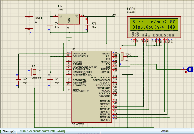
To check of the speedometer and odometer are working I have replaced the Hall sensor with a Logic state device. During the simulation you can click on the logic state button to trigger the Interrupt and check if the speed and distance covered is getting updated as shown above.
for more detail: Digital Speedometer and Odometer Circuit using PIC Microcontroller
- What microcontroller is used in the project?
The project uses the PIC16F877A microcontroller. - How is speed measured in this project?
Speed is measured by detecting rotations with a magnet and a Hall effect sensor and counting pulses via interrupts and timers. - Can the project display speed and distance on a screen?
Yes, speed and distance are displayed on a 16x2 LCD. - How is the Hall sensor simulated in Proteus?
In simulation the Hall sensor can be replaced by a logic state device or button to trigger interrupts. - Does the project use interrupts and timers?
Yes, the project uses interrupts and timers to count pulses and compute speed and distance. - Is full mechanical motion demonstrated in Proteus simulation?
No, complete moving-object behavior cannot be fully demonstrated in simulation; only LCD operation and pulse triggers are verified. - What is required to verify the LCD operation in simulation?
Load the compiled hex file into Proteus and run the simulation to observe the LCD output.