
Summary of Digital frequency meter using pic microcontroller
Digital frequency meter using PIC16F877 Timer1 counts external pulses on RC0/T1OSO for a 1-second interval. Configure T1CON for counter mode with prescaler 1:1, TMR1CS=1, T1SYNC cleared, T1OSCEN cleared to select RC0, and set TMR1ON to start. Read 16-bit TMR1 (TMR1H:TMR1L) after stopping the timer; interrupts are typically disabled. Example T1CON patterns: 00000010 (ready) and 00000011 (running). The project includes a Proteus circuit and MikroC Pro C code using ms_delay(1000) for the 1 s gate time.
Parts used in the Digital frequency meter by PIC microcontroller using timer 1:
- PIC16F877 microcontroller
- External signal source (pulse generator)
- Proteus simulation environment (circuit for simulation)
- RC0/T1OSO pin connection (pin 15)
- Power supply for PIC
- MikroC Pro compiler (for C code)
- ms_delay built-in delay routine
Here you will see how easily we can make Digital frequency meter by PIC microcontroller using timer 1. To make this project we need clear idea on timer 1 module of PIC16F877 microcontroller. We need to know how we can configure timer 1 module to do our desire work. For that I suggest please refer my previous post “Timer Modules in pic16f877 microcontroller”.
As we know
frequency = Number of full circle per second.
So for making frequency meter we have to count number of positive pulses for external signal which we have to measure. As I mention earlier we have to configure T1CON (Timer1 Control Register) properly as per our requirement. For reading external clock (or pulse) we normally set the prescaler 1:1 ratio. It means we do not delay the sampling of the external pulse, but treat the external clock as it is to count number of pulses for specified time duration.
So if we run Timer 1 as a counter mode, there are two pins we can use to apply the external clock pulse RC0/T1OSO and RC1/T1OSI. Selection of one of them is controlled by the T1OSCEN bit.
Setting the bit selects RC1/T1OSO and clearing it does for RC0/T1OSI. In our project as we use counter mode is synchronous, we clear the T1SYNC bit. For TMR1CS bit, we set it for external clock counting. Finally, we set the TMR1ON bit to start the Timer1 module. Counting of the rising edge of the external clock pulse would increase the TMR1 registers by one for every external clock. And TMR1 register made with two 8 bit register TMR1L and TMR1H.When the content of TMR1 crosses from FFFFh to 0000h, the Timer1 interrupt bit TMR1IF would be set, if interrupt is enabled. Usually, when we count number of pulses within a period, we disable the interrupt, and after the lapse of the time, we stop the timer and read the content of TMR1 register.
To make our project “Digital frequency meter by PIC microcontroller using timer 1” Then what will be our bit pattern of TICON register? For counting external clock pulses entered to the pin 15 RC0/T1OSO, bit pattern of T1CON register would be 00000010. When we start the counting, we set the TMR1ON, bit0 of the T1CON and that time bit pattern of T1CON register will be 00000011.
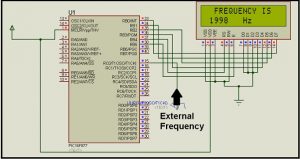
In bellow you see the circuit diagram for simulation in Proteus for our project “Digital frequency meter by PIC microcontroller using timer 1 “.
In bellow you will find the complete c code written in mikro c pro for pic. Here i used inbuilt delay program ( ms_delay(1000)) for 1 sec time interval.
Source: Digital frequency meter using pic microcontroller
- What is measured by this project?
It measures the frequency by counting external pulses per second using Timer1 on PIC16F877. - Which pin is used for external clock input?
The external clock input is applied to RC0/T1OSO (pin 15). - How is Timer1 configured for external pulse counting?
Set prescaler 1:1, TMR1CS=1 for external clock, clear T1SYNC for synchronous counter, clear T1OSCEN to select RC0, and set TMR1ON to start. - What T1CON bit pattern starts the counting?
T1CON bit pattern is 00000011 when counting is started (TMR1ON set). - How long is the counting interval in the example?
The example uses a 1 second interval using ms_delay(1000) in MikroC Pro. - How are the pulse counts read from Timer1?
Stop the timer after the interval and read the 16-bit TMR1 value from TMR1L and TMR1H registers. - What happens when TMR1 overflows?
When TMR1 crosses from FFFFh to 0000h, the TMR1IF interrupt flag is set if interrupts are enabled. - Are interrupts used during counting in this project?
No, interrupts are usually disabled while counting pulses and the timer is read after the time lapse.
