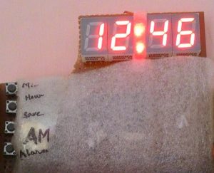
Summary of Digital clock ds1307 using PIC microcontroller
This article details the construction of a digital clock using an 8051 microcontroller. It outlines eight essential electronic components required for assembly, including the AT89S52 microcontroller, 7-segment displays, and a crystal oscillator. The project utilizes interrupt properties to achieve precise one-second counting and includes visual indicators like LEDs for AM/PM status and alarm functions, alongside a piezo buzzer and push switches for user interaction.
Parts used in the Digital Clock Project:
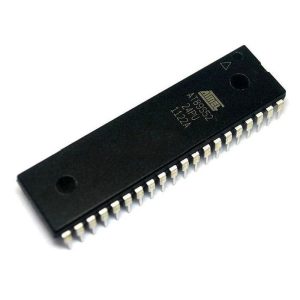
- Microcontroller (AT89S52-8051 family)
- 7 segment display
- Crystal oscillator (12MHz)
- Capacitor (10uF, 33pF/22pF)
- LEDs
- Resistances (330 Ohm)
- Buzzer (piezo)
- Push switches
Step 1: COMPONENTS REQUIRED
6 components needed :
1. Microcontroller (I have used AT89S52-8051 family), any programmable microcontroller can be used.
2.7 segment display
3.Crystal oscillator (12MHz)
4.Capacitor (10uF, 33pF/22pF)
5.LEDs
6.resistances (330 Ohm)
7.buzzer (piezo)
8.push switches
And I’m not including soldering iron, wire, flux….. electricity !!! help me out 🙂
Step 2: Circuit Diagram
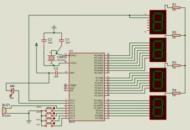
This is the circuit diagram of the digital clock using 8051 microcontroller.
As we can see the microcontroller is connected to three 7 segment display with distinct ports not multiplexed and the last hour digit is only connected to a pin as it only shows 1.
LED and buzzer are self explanatory according to the code.
1 of the LED is for AM and I have connected another LED not shown in the figure for alarm.
Crystal Oscillator of 12MHz is connected to clock speed and attaining the exact 1second counting using the interrupt property of the microcontroller.
THE MIDDLE LEDS DENOTING SECOND ARE CONNECTED TO “28TH AND 32ND” PIN.
Please pardon me, 3 LEDs aren’t shown in the circuit diagram for my laziness.
28th pin LED: first 30 second blink
32nd pin LED: rest 30 second blink
****contributing to a whole minute!!*** i’m sure after this project I came to know 60 second makes a minute!!! WOW
Source: Digital clock ds1307 using PIC microcontroller
-
What microcontroller is used in this project?
The author used an AT89S52 from the 8051 family, though any programmable microcontroller can be used. -
How is the exact one second counting achieved?
A 12MHz Crystal Oscillator is connected to attain exact counting using the interrupt property of the microcontroller. -
How are the 7 segment displays connected?
The microcontroller connects to three 7 segment displays with distinct ports that are not multiplexed. -
Which pins control the middle LEDs denoting seconds?
The LEDs are connected to the 28th and 32nd pins, where the first blinks for the initial 30 seconds and the second for the rest. -
What is the purpose of the extra LED mentioned in the text?
One LED indicates AM status, and another is connected for the alarm function. -
Does the last hour digit use multiple pins?
No, the last hour digit is only connected to a single pin because it only shows the number 1. -
Can other types of microcontrollers be used instead of the AT89S52?
Yes, the article states that any programmable microcontroller can be used for this project.