Summary of DHT22 (AM2302) Digital Humidity and Temperature Sensor Proteus Simulation
The article explains the DHT22 (AM2302) digital humidity and temperature sensor, its 1-wire communication with a microcontroller, data format (16-bit RH, 16-bit temperature, 8-bit checksum), example conversions, negative temperature encoding, and the start/response timing. It notes Proteus support requires version 8.1+, and describes a PIC18F4550 Proteus simulation using the internal 8 MHz oscillator with MCLR disabled.
Parts used in the DHT22 (AM2302) Proteus Simulation:
- DHT22 (AM2302) sensor
- PIC18F4550 microcontroller
- Proteus simulation software (version 8.1 or higher)
- Single data wire connection (1-wire bus)
- Power supply (as required by DHT22 and PIC18F4550)
- Connections for internal oscillator configured at 8 MHz
- Configuration to disable MCLR
Like the DHT11, the DHT22 is a digital humidity and temperature sensor which has more benefits than DHT11 like: High precision and range.
If we want to understand this topic we have to read the DHT22 datasheet and see how this device works and its characteristics.
Note that the DHT22 is available only on Proteus version 8.1 or higher, version 8.0 or later will not work therefore you have to update your version.
From the datasheet:
1-wire bus is used for communication between MCU and DHT22, which means that the sensor communicates over only one-wire with the master device (microprocessor or microcontroller), by this wire the DHT22 sends/receives data to/from the master device.
Illustration of our 1-wire bus:
DATA=16 bits RH data+16 bits Temperature data+8 bits check-sum
Example: MCU has received 40 bits data from AM2302 as
0000 0010 1000 1100 0000 0001 0101 1111 1110 1110
16 bits RH data 16 bits T data check sum
Here we convert 16 bits RH data from binary system to decimal system,
0000 0010 1000 1100 → 652
Binary system Decimal system
RH=652/10=65.2%RH
Here we convert 16 bits T data from binary system to decimal system,
0000 0001 0101 1111 → 351
Binary system Decimal system
T=351/10=35.1℃
When highest bit of temperature is 1, it means the temperature is below 0 degree Celsius.
Example: 1000 0000 0110 0101, T= minus 10.1℃
16 bits T data
Sum=0000 0010+1000 1100+0000 0001+0101 1111=1110 1110
Check-sum=the last 8 bits of Sum=1110 1110
When MCU send start signal, DHT22 change from standby-status to running-status. When MCU finishes sendingthe start signal, DHT22 will send response signal of 40-bit data that reflect the relative humidity and temperatureto MCU. Without start signal from MCU, DHT22 will not give response signal to MCU. One start signal for one
response data from DHT22 that reflect the relative humidity and temperature. DHT22 will change to standby status when data collecting finished if it don’t receive start signal from MCU again.
Interfacing PIC18F4550 with DHT22 (AM2302) Proteus simulation:
response data from DHT22 that reflect the relative humidity and temperature. DHT22 will change to standby status when data collecting finished if it don’t receive start signal from MCU again.
Interfacing PIC18F4550 with DHT22 (AM2302) Proteus simulation:
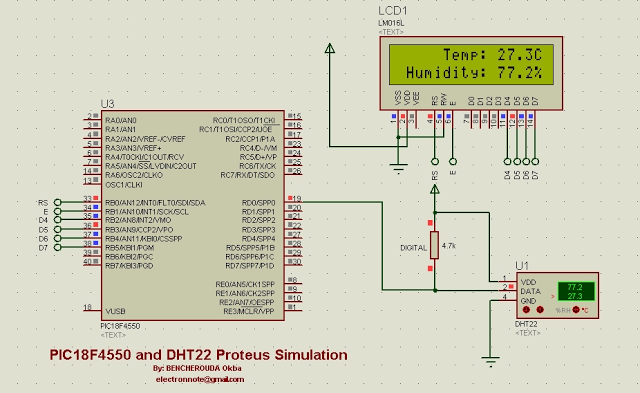
The picture below shows a Proteus circuit diagram of the simulation:
Internal oscillator is used at 8MHz and MCLR pin is disabled.
- What communication bus does DHT22 use?
DHT22 uses a 1-wire bus for communication between the sensor and the master device. - How many bits of data does DHT22 send per reading?
DHT22 sends 40 bits: 16 bits humidity, 16 bits temperature, and 8 bits checksum. - How is relative humidity calculated from the 16-bit RH data?
Convert the 16-bit RH binary to decimal and divide by 10 to get percent RH. - How is temperature calculated from the 16-bit temperature data?
Convert the 16-bit temperature binary to decimal and divide by 10 to get degrees Celsius; highest bit 1 indicates negative temperature. - What indicates a negative temperature in DHT22 data?
If the highest bit of the 16-bit temperature data is 1, the temperature is below 0°C. - What must the MCU do to receive data from DHT22?
The MCU must send a start signal; without it DHT22 will not respond with data. - How often does DHT22 respond after a start signal?
One start signal elicits one 40-bit response; the sensor returns to standby until it receives another start signal. - Which Proteus versions support the DHT22 component?
DHT22 is available only in Proteus version 8.1 or higher; version 8.0 or earlier will not work. - What PIC configuration was used in the Proteus simulation?
The simulation used the PIC18F4550 with internal oscillator at 8 MHz and MCLR disabled.