Summary of Development board for Attiny84 Microcontroller
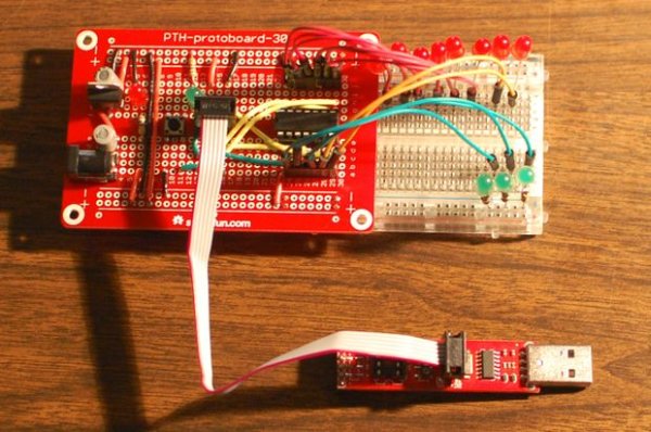
This project builds a solderable development board for the ATtiny84 microcontroller, providing power regulation, ICSP programming header, chip socket, reset switch, and optional indicator LED to support Arduino IDE usage and AVR assembly experiments. The guide details powering from a 9V battery through a 7805 regulator, wiring capacitors and LED, installing an ICSP header and ATtiny84 socket, and wiring reset and indicator circuits.
Parts used in the Development board for Attiny84 Microcontroller:
- SparkFun Solder-able Breadboard (Perma-Proto)
- 2.1mm barrel jack
- 2 × 10µF electrolytic capacitors
- 7805 voltage regulator
- 2 × 330–560 Ω 1/4 Watt resistors
- 2 × 5mm LEDs (red and green)
- 22 gauge hookup wire (Red, Black, Yellow, Green)
- 9 Volt battery clip
- 9 Volt battery
- ATtiny84 microcontroller
- 14-pin IC socket
- IDC breadboard helper (ICSP header)
- 6mm pushbutton switch (reset)
- Tiny AVR Programmer
- 6-pin Socket/Socket IDC cable
- 2×3 male header
- Male headers
- Female headers
This is a development board for Attiny84 microcontroller. Tha Attiny84 chip has 11 pins addressable with the Arduino IDE, 8k of flash memory for program storage, and 512 bytes of RAM available for the stack and program variables.
One feature of the Attiny84 that is very nice for assembly language programmers is unlimited access to all eight pins on the port A registers. They can be used for digital write, digital read, and analog read functions with or without internal pull-up resistors enabled. And four of them can be used for PWM writes. I am planning to use this board to try to expand my very limited knowledge of AVR assembly language.
 You will need:
SparkFun Solder-able Breadboard https://www.sparkfun.com/products/12070
2.1mm barrel jack http://www.adafruit.com/products/373
2 – 10mf electrolytic capacitors https://www.sparkfun.com/products/523
7805 Voltage regulator http://www.adafruit.com/products/2164
2 – 330-560 Ohm 1/4 Watt resistor (purchased locally)
2 – 5mm LEDs, one red one green (purchased locally)
22 gauge hookup wire (I used Red, Black, Yellow, and Green, purchased locally)
9 Volt battery clip http://www.adafruit.com/products/80
9 Volt battery (purchased locally)
Attiny84 micro controller https://www.sparkfun.com/products/11232
14 pin IC socket https://www.sparkfun.com/products/7939
IDC breadboard helper http://www.adafruit.com/products/2105
6mm Pushbutton Switch https://www.sparkfun.com/products/97
Tiny AVR Programmer https://www.sparkfun.com/products/11801
6-pin Socket/Socket IDC cable http://www.adafruit.com/products/371
2×3 male header https://www.sparkfun.com/products/12807
Male Headers https://www.sparkfun.com/products/116
Female Headers https://www.sparkfun.com/products/115
I wish it was possible to purchase all these parts from one supplier to save on shipping but that is not the case. Many of these parts are only available from Sparkfun, and to the best of my knowledge, the IDC breadboard helper is only available from Adafruit.
Step 1: Building The Power Supply
In my diagrams I am using the Adafruit 1/2 Sized Perma-Proto board. I am recommending the SparkFun part because the holes for the power rails line up with a standard breadboard. On the Adafruit part the holes are closer together. This is not to criticize the Adafruit part, but the Sparkfun part is better suited for this project.
The first part to solder is the 2.1mm barrel jack. In order for it to fit it is necessary to cut off the lead on the side of the part. (see picture) Solder the barrel jack into holes A-1 and A-3. Next solder red and black wires for the capacitors and voltage regulator as shown in the diagram. Solder the capacitors like in the diagram. The longer positive lead goes in the column with the red wire. The negative lead is shorter and there is a stripe on the side.
Now solder the voltage regulator as shown.Finish the power supply by soldering the power on LED circuit and the bridge wires to the other set of power rails. The longer lead on the LED is the anode, it goes in the column with the resistor.Plug in the battery to test your work. The LED should light and the voltage regulator should not get hot.
Step 2: Chip Socket and ICSP header
The part called an IDC breadboard helper is the In Circuit Serial Programming (ICSP) header. I don’t have the Fritzing part so you will just have to imagine that it is there. It looks like the part in the second picture. The third picture is it’s pinout.
 Solder the In ICSP header into Holes E-14 through E-16 and F-14 Through F-16. Wrap a small rubber band around it to hold it in place while soldering the first pin.I don’t have the Fritzing part so I used a 556 timer to represent the 14 pin IC socket.Solder the socket, the notched end points toward the power supply.Solder the wires to the power and ground rails, and the wires connecting the chip to the ICSP connector, follow the diagram.
Step 3: Reset Switch and Indicator LED
Solder the circuit for the reset switch, follow the diagram.
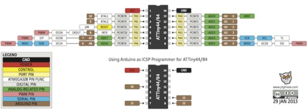
The onboard indicator LED is optional, some people want it and some don’t. I put it on Arduino pin 10, that is PB0 if you are into assembly language. You may want to put it on a different pin, if so look at the pinout chart on the last page of this instructable. The LED and Resistor will pull the pin low, so if you use is as an input you will need to check it for high. If you move it to a different pin I would recommend not using Arduino pins 0 – 7 so the assembly language programmer has unlimited use of all eight pins on porta.
For more detail: Development board for Attiny84 Microcontroller
- What microcontroller is this development board for?
The board is for the ATtiny84 microcontroller. - How is the board powered?
It is powered by a 9V battery connected via a 2.1mm barrel jack and regulated by a 7805 voltage regulator. - Which part provides the ICSP connection?
The IDC breadboard helper is used as the ICSP header for in-circuit serial programming. - Where is the ATtiny84 socket placed?
A 14-pin IC socket is soldered onto the board with the notched end pointing toward the power supply. - What components are used for the power supply smoothing?
Two 10µF electrolytic capacitors are used across the power rails for smoothing. - How is the reset implemented?
A 6mm pushbutton switch is soldered as the reset switch following the diagram. - Is there an onboard indicator LED?
Yes, an optional indicator LED is included and connected to Arduino pin 10 (PB0) in the example. - Can the LED be moved to a different pin?
Yes, you may place the LED on a different pin; the guide warns against using Arduino pins 0–7 to keep all porta pins available for assembly use. - What programmer is recommended for uploading code?
The Tiny AVR Programmer is used with a 6-pin IDC cable to program the ATtiny84 via the ICSP header.