
PIC ICSP gives you a convenient way of programming PIC Micros without removing the chip from the development or production board.
Note: ICSP stands for In Circuit Serial Programming.
All you need is a programmer that provides the ICSP connector (usually a six pin molex/dupont connector) which you plug into your target board. For example PicKit2/Pickit3 uses the ICSP connections shown in the diagrams below. .
 The programmer is controlled from the PC using an IDE and for the PicKit2/3 this will be MPLAB X IDE. This program loads up your hex file (that you want to burn into the PIC device) and sends commands to the programmer to do that job via the ICSP signals that you connect to your PIC device (see below).
Note: Older programmers that are labelled Serial or Parallel both send serial data to the PIC microcontroller through the PIC ICSP circuit. The ‘Serial’ or ‘Parallel’ description refers only to the interface used from the PC to the PIC ICSP circuit. Modern programmers such as the PicKit2/3 use a USB port. Again, a USB programmer is merely refering to the PC interface and the output at the ICSP connector is exactly the same as all the others.
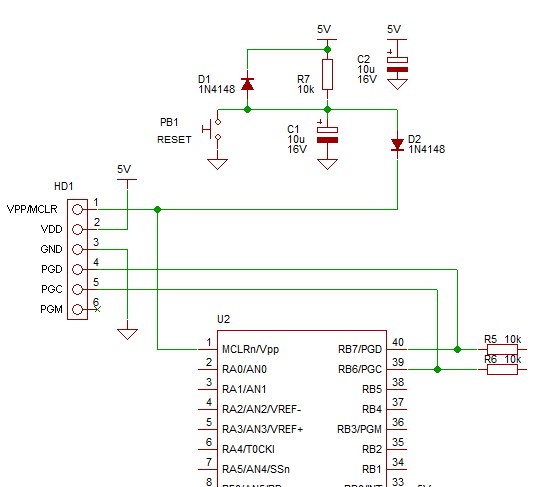
Here a PIC ICSP and full reset circuit :
Note: This is for the 16F877 and other 40 pin chips that have the same pinout for the ICSP connector e.g. 18F2550 (or at least MCLR at top left and PGD and PGC at top right).
Notes on the above circuit:
The PIC ICSP reset circuit is an over the top over-protected circuit that you would use if you were being ultra cautious or producing a developed PCB design. It stops high volts going back to the 5V power line (D2), has a fast shut down when 5V is off (D1) – allows fast rest from power Off-to-On and has a defined rise time for a delayed reset start.
The PGM pull-down resistor (can be connected to PGM pin – note shown here) is not really needed as you can always program the device using a high volt ICSP programmer (see below for more on LVP Low Volt Programming using PGM). If the LVP mode is not turned off then the pin is not usable as normal I/O it can only be used for PGM signal.
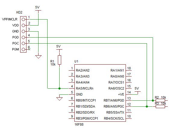
Simplified PIC ICSP Connection
Here is a simplified ICSP connection for lab development:
Note: When you develop a board quickly e.g. on a solderless breadboard you only really need a 10k pullup from MCLRn to 5V – sometimes you will program that pin as an input in which case the reset is handled internally. With the 10k only; When programming, Does it put high voltage against the 5V? – Yes, however – the lab bench PSU will be fine (since there is (13V-5V)/10k ~ 10/10k = 0.1mA flowing)! – Put a diode in if you really want (you do loose 0.6V though).
Alternatively turn off the PSU and power the chip from the PicKit3 (the power setting is in MPLAB X IDE).
PIC ICSP Signals
PIC ICSP provides 6 connections from the pic ICSP programmer to your board as follows :
| 1. VPP (or MCLRn) | Programming voltage (usually 13V). |
| 2. Vcc | Power (usually 5V). |
| 3. GND | Ground (zero volts). |
| 4. PGD – Data | usual port and connection RB7. |
| 5. PGC – Clock | usual port and connection RB6. |
| 6. PGM – LVP enable | usual port and connection RB3/RB4. |
 Note: With the connections made in this order on the connector it will not matter if the connector is placed the wrong way round as GND and VCC are then applied to clock and data. If VCC and GND had been at opposite ends of the connector then there would be a problem.
same way as the standard PicKit2/3 = good!
VPP Signal (Signal a programming action)
Vpp connects to the reset input of the pic microcontroller labelled MCLR. During programming or verify this signal is raised to the programming voltage (13.5V) – or VCC+3.5V. This signals to the microcontroller that programming/verification is about to start and for older parts, supplies current.
Note: Older pic micros used this line to directly power the programming circuit that updates the Flash memory. So this connection had to supply some current. With the newer parts that allow LVP (Low Volt programming) the programming voltage is generated internally so the Vpp signal from the pic ICSP is only used as an indicator i.e. it doesn’t have to supply current.
For more detail: Details of PIC ICSP and how to use it for pic microcontrollers.
About The Author
Ibrar Ayyub
I am an experienced technical writer holding a Master's degree in computer science from BZU Multan, Pakistan University. With a background spanning various industries, particularly in home automation and engineering, I have honed my skills in crafting clear and concise content. Proficient in leveraging infographics and diagrams, I strive to simplify complex concepts for readers. My strength lies in thorough research and presenting information in a structured and logical format.
Follow Us:LinkedinTwitter