Summary of PicChess
This article details a custom microcontroller-based chess game capable of playing against an intelligent computer on a VGA monitor. Developed by an electrical engineering student, the project features audio effects, a clock, temperature sensing, and a modular codebase written from scratch using a DSPIC33F128MC804 processor. The system includes a PS2 keyboard interface, external flash memory, and real-time clock functionality, demonstrating advanced video and audio generation techniques on a single chip.
Parts used in the PicChess:
- CRYSTAL 20MHz
- CRYSTAL 32.768 kHz
- 74HCT14D
- SST25VF016B Flash Memory
- DSPIC33FJ128MC804-PT Processor
- LM380 Audio Amplifier
- LM35 Temperature Sensor
- LM317 Voltage Regulator
- 7812 Voltage Regulator
- ST232 RS232 Transceiver
- LED 5MM
- 1N4004 Diodes
- Resistors (220R, 390R, 1k, 10k)
- Capacitors (22pF, 100nF, 10uF, 470uF)
- DB9 Female Connector
- DB15 Female Connector
- MINI-DIN6 Connector
- Pinhead Bar
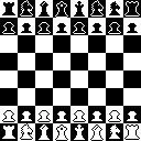
This project is a micro controller chess game. The objective has to be able to play chess on a VGA monitor, including an intelligent computer to play against. This all has been accomplished with a microcontroller.
I started this as a project for the college ( I am a Electrical Engineering student ), but it has grow way beyond that. Now it is a complete chess game with a video output, keyboard for user interface, audio for some sound effects, a clock, a temperature meter. All the code was written from scratch, so any questions about the code you can ask me. I took a lot of time to write all this down, and to make the video and audio routines. The code is all well commented (almost all in English) and modular, it shouldn’t be hard to understand.
The source code (attached as a RAR file) was all divided in simple modules, so it’s easy to debug and re-use. Some cool techniques where used in the routines that are worth a look. The division of the source code is as follows :
- Audio
- Keyboard
- Video
- Graphics Routines
- Serial
- Temperature sensing
- External Flash Memory (NVM)
- Real Time Clock and Calendar (RTCC)
- Analog Clock
- Chess Engine
- Chess Human Interface
- Chess Graphics
- Conway’s Game of Life
Each section of the code is explained in the next Steps of the instructable, the entire code is huge (108 pages) so i will just scrach the top of it. The routines are written in a non-blocking way, so adding more stuff it’s plain.
In the end i had a nice game, not so hard but funny.
Thanks to to my friend Igor for drawing the pieces for me (I suck in Paint).
And if you like the project, and feel it deserves to win, vote in the Microcontroller Contest,and on the Toy contest.To vote go to the following links:
Microcontroller Contest
Toy Challenge
Arthur Benemann, Brazil 2011
 picChess.rar9 MB
 schematic.pdf21 KB
Step 1: Hardware
For the hardware the main challenge is to select a processor with power to handle the audio and video, and still have enough power to run the chess engine. The most powerful micro that i had at hand was a DSPIC33F128MC804 from microchip, that i bought to start playing around with the DSPIC33F family. And this seemed a good project to do this.
I know that this micro was supposed to be used for motor control, it has all those nice peripherals and the DSP instruction , but let’s do not use this stuff now. The things that are interesting are the SPI module that can go up to 10MHz, 40 MIPS core, 8 DMA channels, 4 Output Compare modules, audio DAC.
The clock is run at 80MHz this makes the use of the full processor power, and also can be scaled to get a 10MHz clock for the SPI module this is necessary by the video routine. This clock rate is obtained by the PLL block in the DSPIC33F.
If i don’t know what is DMA its a feature that allows some peripherals to transfer memory to or from the data memory without CPU intervention. (wiki reference)
So with the processor chosen the rest it’s straight forward.
- Keyboard PS2 connection is as simple as two resistor just for precaution (the 5v input pins of the micro must be used).
- Serial RS232 using a ST232 as transceiver, no interface needed for 3v3.
- The temperature sensor , a LM35 (10mV/ºC) , just need a low pass filter in the output. External
- SST25VF016B Flash memory comunnicate via SPI and is 3v3 so just a direct connection, two resistor are added just in case there is a software problem and two inputs accidentally are connected together.
- Audio output from the DAC it’s a 0.7v peak signal. Amplification and ac coupling are made by a capacitor and a LM380 in the typical application from the datasheet, it’s capable of outputting 2W with low distortion.
- VGA signal its composed of 2 TTL signal, just a resistor for interfacing, and three analog RGB signals. The input impedance of a monitor is 75 Ohms so just a resistor would fit, but the signal must have a 0,7 amplitude for full intensity in the screen, by Ohms law this gives 9.3mA more than the maximum current of the processor. A 74HCT14 inversor gives the current gain.
The power supply has three output rails. A 5V regulated by a 7805, for the high voltage chips. A 3v3 rail powers the processor and the flash memory, to get 3v3 a LM317 is used just as described in the datasheet. The amplifier is connected to the unregulated supply because it needs the higher voltage to power the speaker.
I designed little modules to plug in a bread board so they can be reused. All these modules are in the project files.Some i have built in a pre drilled pcb so there are no files, but these are simple to be made.
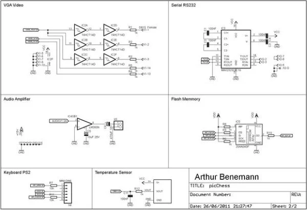
In the beginning of this step there are pictures of the project mounted in my breadboard, the Schematic is also there, but the eagle files are in the project files.
Parts List:
Qty Value
1 CRYSTAL 20MHz
1 CRYSTAL 32.768 kHz
1 74HCT14D
1 SST25VF016B
1 DSPIC33FJ128MC804-PT
1 LM380
1 LM35
1 LM317
1 7812
1 ST232
1 LED 5MM
2 1N4004
2 220R 1/8W
1 390R 1/8W
5 1k 1/8W
5 1k 1/8W
3 10k 1/8W
4 22pF 50V
7 100nF 16V
4 10uF 25V
1 470uF 16V
1 DB9 Female
1 DB15 Female
1 MINI-DIN6
1 pinhead bar
For more detail: PicChess
- What is the main processor used in this project?
The project uses a DSPIC33F128MC804 from Microchip. - How is the clock speed configured for the processor?
The clock runs at 80MHz obtained by the PLL block to utilize full power and scale down to 10MHz for the SPI module. - Does the project support audio output?
Yes, it uses an internal DAC with an LM380 amplifier to output 2W with low distortion. - Can the user interface via a standard keyboard?
Yes, a PS2 keyboard connection is implemented using two resistors for precaution. - How is the VGA signal generated?
The VGA signal uses two TTL signals and three analog RGB signals, amplified by a 74HCT14 inverter for current gain. - What type of external memory is utilized?
An SST25VF016B Flash memory communicates via SPI at 3v3. - Is there a feature for temperature monitoring?
Yes, an LM35 sensor is used with a low pass filter on the output. - How is the power supply organized?
It has three rails: 5V regulated by a 7805, 3v3 powered by an LM317, and an unregulated supply for the amplifier.