Summary of Design and Development of an Automated Home Control System Using Mobile Phone
This paper describes an Automated Home Control System (AHCS) that uses a mobile phone as a modem to send DTMF commands to a PIC16F84A microcontroller, which decodes tones and drives relays to switch four household appliances. The design includes a power supply, DTMF decoder (HT8870), switching transistors and relays, and a phone configured to auto-answer.
Parts used in the Automated Home Control System:
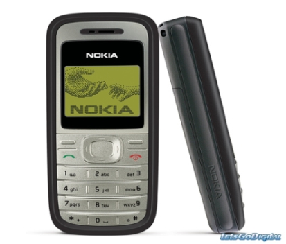
- Nokia 1200 mobile phone (used as modem)
- DTMF decoder IC HT8870
- PIC16F84A microcontroller
- Crystal oscillator (4 MHz) for PIC
- Crystal (XTAL1) for DTMF decoder
- Relays (4 channels for appliances)
- Switching transistors (for driving relays)
- Base resistors for transistors
- Flyback diodes across relay coils
- Power supply (5 V DC)
- Coupling capacitor C1 and filter components C2, C3, C4
- Resistors R1, R2, R3 and collector resistance Rc (relay coil resistance ~400 Ω)
Abstract
This paper presents design and development of an Automated Home Control System (AHCS) using mobile phone. A cell (mobile) phone acts as a modem for the control of electrical home appliances. This is achieved when the mobile phone number is dialed and an appropriate command button is pressed. The paper demonstrates how to develop a system that aids the control of remote devices using mobile phones to enable devices without infrared though connected to power sources to be controlled and considering the possibility of users to monitor the status and usage of these devices. It makes use of a programmable interface controller (PIC) to control the switching of the output. This design is customized as a central device for four pieces of home appliances using relay to activate each of the respective electronic gadgets.
Keywords: Automated home control system, mobile phone, modem, programmable interface controller (PIC), relay, Microcontroller, Dual Multi-Tone frequency (DMTF)
World Journal Control Science and Engineering, 2014 2 (1), pp 6-11.
DOI: 10.12691/wjcse-2-1-2
1. Introduction
Initially communication was done by travelling from kilometre to kilometre to deliver messages but now the trend involves talking to people even when they are far away around the globe even to the extent of seeing them using the present day 3G technologies. Now mobile phones can be used to trigger their greatest revolution: by allowing us to run our homes remotely. If you are heading home early on a sunny day to your house driving through traffic in Lagos, your mobile phone can be used to switch on your central air conditioner at the touch of a keypad or even turn on your water heater system on a cold night preparing yourself for a warm shower. Fitted to a kitchen wall, the unit will communicate with tiny transponders attached to air conditioners, fridges, washing machines, microwave ovens and household appliances. Computer chips and digital networks are now so cheap, we can use them where we want, and kitchens and utility rooms are just perfect for “intelligent” improvements. Japan is already transforming domestic life through its new I-mode mobile phone that can take and transmit pictures. One unexpected use includes the ability to buy Coca-Cola cans without handing over cash. Just pass your phone in front of a scanner on one of several hundred I-mode automated vendors in Japan and your credit card account will be debited in exchange for a chilled can of Coke [4].
Controlling device using switches are common. From a few decades, controlling devices using remote control switches like infrared remote control switch, wireless remote control switch, light activated switches are becoming popular. But these technologies have their own limitations. Laser beams are harmful to mankind. Some technologies like infra-red (IR) remote control are used for short distance applications. In such case, if we have system which does not require any radiations or which is not harmful, and cannot travel for a long distance. Hence the need to design and construct a project circuit that does not require any radiations, any laser beam which has no limitation of range, therefore it can be used from any distance ranging from metres to thousands of kilometres using a simple telephone line or mobile phone. This justifies the need to automate and control the home appliances via the use of mobile phone.
 Home automation is a modern technology that gives home owners the ability to take charge and control of the devices placing security and convenience in their homes even when they are not physically at home. Imagine a situation where one is not sure if one turns off an electrical appliance on rushing out of home. One can use an enabled home automation system to confirm the suspicion and turns off the appliance from one’s present location [1, 4].
2. Literature Review
By the early 1980s, the industry moved to infrared, or IR, remote technology. The IR remote works by using a low frequency light beam, so low that the human eye cannot see it, but which can be detected by a receiver in the TV. Zenith’s development of cable-compatible tuning and teletext technologies in the 1980s greatly enhanced the capabilities and uses for infrared television (TV) remotes. Today, remote control is a standard feature on other consumer electronics products, including video cassette recorders (VCRs), cable and satellite boxes, digital video disc players and home audio receivers. And the most sophisticated TV sets have remotes with as many as 50 buttons.
Zenith developed the world’s first wireless trackball TV remote control, called Z-Trak. The remote works like a computer mouse – click the ball and a cursor appears on the TV screen. Roll the ball and the cursor activates control menus hidden in different corners of the screen. Then, activate something from those menu bass, treble, contrast, colour temperature, and channel [5, 6, 8].
According to Sajidullah S. Khan, Anuja Khodustar and Koli, N.A who worked on Home automation appliance (2011) and striking results were obtained in terms of reduction in delay time between the transitions of streams from client to server using Java enabled program.
More so, Kai-Hung Liang, Kuo-Han Kan, and Szu-Chi Tien (2013) who carried out work on the precision positioning with shape-memory-alloy actuators. The result obtained using the inversion of non-linear model with model-reference-adaptive system (MRAS) was robust as regards to external disturbances and the positioning performance [13].
3. Design Procedure / Methodology
In this segment, there will be general overview of the design of some of the circuits, which are used in the realization of this work. These circuits consist of the modem stage, DTMF Decoder stage, PIC Microcontroller stage, switching stage and power supply stage.
3.1. The Modem
The modem receives the signal sent from the user’s phone and sends it to the DTMF decoder which decodes the signal. A regular mobile phone will be used as a modern because of its lower cost and availability. The SIM card of the desired network will be inserted in the phone and its number becomes the access number of the device. The phone is configured such that it automatically answers incoming calls; this is to reduce the need for extra circuitry thereby minimizing the power consumption.
A NOKIA 1200 mobile phone is used as the modem because of its affordability and availability, the audio output of the phone will be connected to the DTMF decoder and its charging port will be connected to a 5v from the power supply which keeps the battery from discharging.
3.2. DTMF Decoder
This system uses Dual Tone Multi Frequency (DTMF) technology of telephone set. Every telephone set has this facility. There are two types of dialing facilities in a telephone system; pulse dialing mode and tone dialing mode. Here this system works on tone dialing mode. The DTMF mode is shortly called as tone dialing mode.
This system is divided into two sections.
1: Remote section
2: Local control section.
When a button is pressed in the telephone set keypad, a connection is made that generates a resultant signal of two tones at the same time. The two tones are taken from a row frequency and a column frequency. Its resultant frequency signal is called a “Dual Tone Multiple Frequency “. These tones are identical and unique.
A DTMF signal is the algebraic sum of two different audio frequencies which are chosen such that they are not the harmonics of each other.
By sending DTMF signals to the telephone exchange through cables or wireless, the server in the telephone exchange identifies these signals and makes the connection to the the intended receiver of the call.
Each of the low and high frequency groups comprise four frequencies from the various keys present on the telephone keypad; two different frequencies, one from the high frequency group and another from the low frequency group are used to produce a DTMF signal to represent the pressed key.
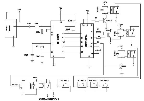
The frequencies are chosen such that they are not the harmonics of each other. The DMTF decoder circuit diagram is depicted in figure below.
When the system number is dialed the modem automatically answers and waits for the user to press a button. When a one (1) is pressed, the DTMF tone flows into U1 through C1 which filters it and R1, R2 which divide the signal. XTAL1 is a crystal which generates the operating frequency of the decoder, C2, C3 filter the oscillation. C4 and R3 determine the response time of the tone.. U1 is the DTMF decoder IC which is a HT8870 chip. It operates on a maximum of 5v DC.
 3.3. Microcontroller Stage
The microcontroller controls the entire operation of the circuit, its receives the decoded signals from the DTMF decoder then processes it and activates or deactivates the corresponding device by sending a logic to enable or disable the relay connected to the load. A microcontroller is used because of its low power consumption and flexibility of its functions [6].
In this design a PIC16F84A is used because it consumes lower power compared to other available microcontrollers. Its program memory contains a 1Kilobyte word which translates to 1024 instructions. Since each 14-bit program memory word is the same width as each device instruction. The data memory (RAM) contains 68 bytes. Data electronically erasable programmable read only memory (EEPROM) is 64 bytes. There are also 13 input/ output (I/O) pins that are user-configured on a pin-to-pin basis. Some pins are multiplexed with other device functions.
The microcontroller receives the signal from the Decoder in form of binary numbers then activates the corresponding device by sending a high logic to the transistor that controls the relay or if a deactivating data is received from the decoder, it sends a low logic to the transistor of the corresponding relay. Crystal XTAL2 generates the frequency needed for the operation of the microcontroller; it is a 4 MHz crystal. The microcontroller operates on a 5vdirect current (DC) supply. The data from the decoder is connected to PORTA while the transistors are connected to PORTB of the microcontroller.
3.4. Switching Transistor Stage
This is a simple electromechanical switch made up of an electromagnet and a set of contacts. The electromagnet is used to operate a switching mechanism, but other operating principles are also used. Relays find applications where it is necessary to control a circuit by a low-power signal, or where several circuits must be controlled by one signal.
The switching transistor switches the relay which powers the Load. The transistor as a switch operates in class A mode. The relay is switched on when the microcontroller (PIC16F84) gives a HIGH output. A base resistor is required to ensure perfect switching of the transistor in saturation. The diode connected across the relay is to protect the transistor from back electromotive force (EMF) that might be generated since the relay coil present is an inductive load [9].
In this paper, Rc is the collector resistance that serves as the resistance of the relay coil, which is 400Ώ for the relay type adopted in this paper.
For more detail: Design and Development of an Automated Home Control System Using Mobile Phone
- How does the system receive commands from the user?
The user dials the system phone number and presses keypad buttons; the modem phone automatically answers and sends DTMF tones to the decoder. - Can any mobile phone be used as the modem?
The paper uses a Nokia 1200 mobile phone as the modem because of affordability and availability; the mobile phone must provide audio output and be configurable to auto-answer. - What technology decodes the keypad tones?
The system uses Dual Tone Multi Frequency (DTMF) decoding via an HT8870 DTMF decoder IC. - How are appliances switched on or off?
The PIC16F84A microcontroller processes decoded signals and outputs logic to switching transistors that drive relays which activate the appliances. - What microcontroller is used and why?
The PIC16F84A is used for low power consumption and sufficient program/data memory and I/O pins for the design. - What protects the transistors from relay coil back EMF?
A diode is connected across each relay coil to protect the transistor from back electromotive force. - How is the modem phone powered to avoid battery discharge?
The phone charging port is connected to the system 5 V power supply to keep the battery from discharging. - Which ports of the PIC are used for inputs and outputs?
Decoder outputs are connected to PORTA of the PIC and the transistors (relay drivers) are connected to PORTB. - What determines the response time of the DTMF decoder?
Components C4 and R3 determine the response time of the DTMF decoder tone detection. - How many appliances does the designed system control?
The design is customized as a central device for four home appliances using relays to activate each gadget.