Brief Description:
The main goal of this project is to design a DC motor controller, We had a DC motor controller that its control circuit has been damaged. Here we are attempting to design a new control circuit for the controller. But before we can design the control circuit, we needed to know the power circuit design. To improve our design and make the most suitable control circuit.
Supplies
Arduino uno.
4N31 OPTOCOUPLERS.
SN74LS04 NOT GATE.
weirs.
Step 1: Checking the Old Controller Power Circuit and Draw It.
Before we can make a control unit, we need to understand the power circuit of the old controller. Here are some useful website that helped to well understand the working principle of it.
https://electronics.stackexchange.com/questions/32…
The next step is to draw the diagram of the power circuit. And i did that many times and this is the final one.
Step 2: Building the First Circuit to Control the Duty Cycle to Control the Mosfet.
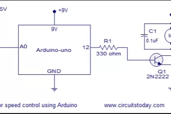
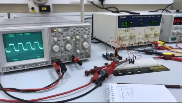
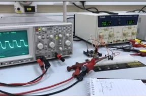
Before connecting the Arduino to the power circuit, we needed to build this circuit and test it. this step has been done by connecting the Arduino to an oscilloscope and test the circuit.
Step 3: Connecting the Arduino Circuit on Test Board and Try It on the Controller.
The Arduino circuit on the previous step has been tested on the power circuit and the Arduino got damaged. So we used a function generator in order to test the power circuit and that did work.
The Arduino couldn’t sent high voltage pulses and after checking the old control unit we saw an optocoupler connected with a mosfet driver in order to send pulses. the output voltage of the old control unit was around 12v. so we need to modify our control circuit to make it suitable.
Step 4: Draw the Old Control Unit Circuit Diagram.
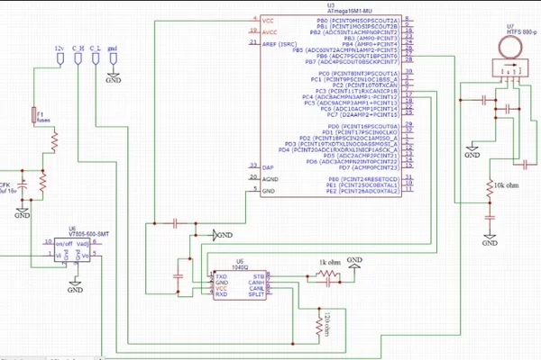
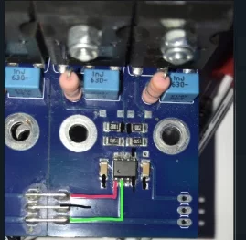
Since we couldn’t run the power circuit using only Arduino, we needed to look for the connection and components of the old control unit. And the old control circuit uses an optocoupler with a mosfet driver connected to the Arduino pin. so the PWM output has been taken from the MOSFET driver on the control board. see the pic on the left. we have a voltage converter from 5v to 12v. and we use that voltage to run the mosfet driver. the PWM pin from the Arduino is connected to an optocoupler which his output connected to the input pin on the mosfet driver.
this circuit couldn’t be done because we didnt find the needed components
Step 5: Building a Control Circuit With Arduino Using an Optocoupler
The circuit in the previous step couldn’t be done because we couldn’t find the needed components.
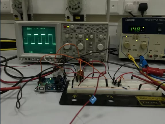
In this step we tried a different circuit to test the power circuit of the controller. we used an optocoupler with the Arduino to control 12v instead of the 5v from the Arduino pin. you can see the output waveform on the right. we also added 2 not gates on the output of the optocoupler to have fully squared waveform.
The motor worked using this circuit, but we couldn’t change the value of the output from the power circuit.
Step 6: Trying to Use the Old Control Unit Components.
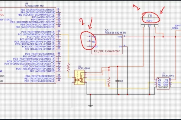
the first picture shows the circuit diagram that we want to build from the old control unit. the other one shows the control board. As you can see the components we need is SMD which we cant use on a test board so, we used some weirs and tried to weld them on the ICs pins. see the last pic.
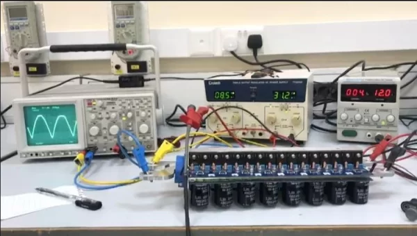
Step 7: Using an Op-amp to Amplify the PWM From 5v to 15 V Maximum.
We used a non-inverting op-amp circuit to amplify the Arduino signal. From the picture above you can see formulas that we needed.
The gain of the op-amp is set using this formula:
a = Vout/Vin = 1+Rf/R2 which give us the following,
a= 1+ 10k/4.7k = 3.1 .
And the Vout= a*v(in).
since we are using the PWM the value of the input in the op-amp is not fixed, it will goes form 0-5 v thus,
when the input of the op-amp is 1v the output will be a*v(in) = 1*3.1 = 3.1v
and when the input of the op-amp is 5v the output will be a*v(in) = 5*3.1 = 15.4v .
here we have a simulated circuit using tinkercad: https://www.tinkercad.com/things/fJzB6WPow5h-copy-of-lab-1a-non-inverting-amplifier-/editel?sharecode=a9nXMYCSCp3gf1MS9GYBwqEMRDl8mOkdB0rbOC5XPoQ
we connected the op-amp circuit with the Arduino and tested the circuit this amplify signal in the lab.
after testing the circuit we connected the circuit to the motor controller and it did work!.