Summary of Dancing Boids
Dancing Boids visualizes audio by FFT-ing ADC samples and driving three boid groups (low, mid, high bands). Each group switches between lattice (crystalline) and flocking behaviors based on band energy, using fixed-point math, DMA for ADC sampling, and PIC hardware timers/peripherals to achieve real-time animation on a TFT display.
Parts used in the Dancing Boids:
- PIC32 microcontroller (with DMA and ADC peripherals)
- Electret microphone
- Microphone pre-amplifier circuit
- 3.5mm auxiliary audio jack (AUX) input circuit with RC high-pass filter and DC bias
- DPDT slide switch (two SPDT switches used) for input mode selection
- TFT display (ILI9340-based 240x320)
- ProtoThreads threading library and supporting headers (pt_cornell_1_3_2.h)
- Graphics libraries (tft_master.h, tft_gfx.h)
- Fixed-point math support (_Accum data type)
- Timer peripherals (Timer3 for ADC sample trigger, Timer4 for profiling)
- Direct Memory Access (DMA) channel for ADC to memory transfers
Introduction and High-Level Design
When we were brainstorming ideas, each one of us had different interests. Max wanted to do an audio-related project as he is working for McIntosh, a company that designs and manufactures handcrafted legendary home audio systems. Ben wanted to make something that would be highly visually appealing. Alek wanted to take in something from the physical world and use it to either play a game or draw something on the TFT, and we all wanted it to be fun to play with.
After throwing around ideas, we settled on what we called “Dancing Boids.” The general idea is that we take in audio input through either a microphone or an audio jack and the boids from lab 2 respond to that input in interesting ways. This project was really rewarding because it synthesized different elements from the previous 3 labs. It is quite obvious how this lab relates to lab 2, The Boids Lab. In lab 1 we did digital to analog conversion and in our project we were tasked with doing the inverse as we took in analog signals from the mic and turned them into a digital representation that could be analyzed. In our system we looked at changes in the audio signal’s energy level, and interestingly, this analysis mirrored some of the analysis we performed on the signal coming from the potentiometer in lab 3, The PID Controller Lab.
In our system we perform a fast fourier transform (FFT) on the digitized audio signal and store this information in an array. We thus gain information about the frequency components of the audio signal. The array containing the frequency components of the signal is divided into 3 adjacent and nearly equally sized bands. The first band represents low frequency content of the signal. The second band represents medium frequency content, and the third band represents high frequency content. The sampling frequency was chosen so that the frequency content present in this array would be entirely in the audible range.
In our system we also have 3 groups of boids. Each group of boids is tied to one of the frequency bands that we defined in the array. Thus each group of boids can be thought of as a visual representation of a particular frequency range. Information from each one of these bands is extracted individually, and based on this information, instructions are given to the corresponding group of boids for that particular band. If the energy level of the band is above a certain threshold, then the boids representing that band assume typical boid behavior. If the energy in the band is below that threshold, then the boids representing that band assume what we call lattice formation. Lattice formation was defined in a way that resembles crystalen structure. In this way when their is complete silence, you have three of these snowflake like structures floating around the screen, and when the boids hear content in their specific frequency range, they break free and majestically fly around the screen. These simple rules yielded quite interesting results when we played the system music. A short demonstration of the system can be seen below.
####A QUICK DEMO###
from IPython.display import HTML
HTML("""
<video width="560" height="315" controls>
  <source src="video.mp4" type="video/mp4">
</video>
""")
Boids
Each dot in our system is referred to as a boid. This is in reference to Boid’s Algorithm. Boid’s Algorithm is utilized to animate these dots so that they resemble something you might see in nature such as birds flocking or a school of fish swimming. The boids have what are called protected ranges (smaller) and visual ranges (larger). In Boid’s Algorithm, each boid looks at every other boid. If another boid is within its visual range it adjusts its velocity to move with it, and thus you see boids flocking together. If another boid is within its protected range, meaning that it is too close, it adjusts its velocity to separate from that boid until it is out of its protected range. There are various parameters you can adjust in Boid’s Algorithm that affect things like how much boids try to avoid other boids and how much boids try to flock with each other. Adjusting these parameters is how we achieve the boid state and the lattice state shown above. This is a high-level overview of Boid’s Algorithm which we implemented in Lab 2. For a more detailed look into the algorithm you can visit the Lab 2 webpage https://people.ece.cornell.edu/land/courses/ece4760/labs/s2021/Boids/Boids.html which can also be found on the course webstie.
Even just knowing the basics of boids algorithm, it is apparent that the more boids there are the slower the algorithm becomes because every boid must consider every other boid. In fact, without any optimization, the algorithm is O(N^2).
However, in our system each boid only looks at the other boids in its group meaning that it only looks at roughly one third of the other boids. Technically, it looks at all the other boids first checking that a boid is in the same group as itself before moving on to any of the more expensive computation, but this check is fairly insignificant and thus, performance wise, it is similar to each boid only considering the other boids that are in its group. This property combined with the fact that we kept the number of boids fairly low, allowed us to achieve a crisp animation that looked fluid to the human eye even while doing other tasks such as performing FFT.
Even with this property we needed to incorporate some other techniques to achieve the performance we were looking for. First, we needed to use fixed point arithmetic instead of floating point arithmetic. Fixed point arithmetic is a way of representing fractional numbers with a fixed length fractional part and a fixed length integer part. This property yields a huge efficiency increase when doing arithmetic operations compared to the floating point data type’s arithmetic performance. In our code we use the _Accum data type as our fixed point data type.
Additionally, we offloaded tasks to the PIC’s hardware peripherals to free up CPU cycles. This method of increasing performance is described more in depth later on.
Software
The first major part of process is to perform analog to digital conversion which was done by the ADC hardware peripheral on the PIC. This hardware peripheral was set up in software along with a DMA channel. How and why this was done is discussed in more detail below in the “Harware+Software Co-Design” section. These two peripherals working in tandem allowed us to end up with a digitized audio signal on which we could perform a fast fourier transform (FFT).
The FFT was performed in its own thread, protothread_fft. Here we would call an FFT function that would use a precomputed sine wave to break down an array of time domain samples into two separate arrays, the real and imaginary components of frequency domain elements. Before feeding our samples into this function, we first applied a Hann window, using a for loop, to our samples in order to prevent spectral leakage. Then we would feed our 256 samples into the FFT function and receive the two arrays containing the real and imaginary frequency information. As we wanted to influence the Boids behavior by looking at the energy in different frequency bands, we needed to compute the magnitudes of the presence of different frequencies. This was done by computing the magnitude of the real and imaginary components at each bin, which we did by using the alpha max beta min formula to save computational space.
We referred to the spaces in the FFT analysis array as bins. The content of the bins represented the energy level, or magnitude, of given frequency components in the audio signal. Thus if a bin had a big value, you knew that a lot of the frequency represented by that bin was present in the audio signal.
As previously mentioned, the result of FFT analysis was split into 3 bands, one for each group of boids. Band one was bin 5 through bin 42. This was the low frequency band. We started at bin 5 because we did not want to include any DC component of the signal or any extremely low frequency components. The next band was comprised of bin 43 through bin 84. This was the medium frequency band. The last band, the high frequency band, was comprised of bin 85 through bin 128.
The sum of bins’ values across a band were taken which was the total energy level of the band. If the sum across any given band exceeded some threshold that we set, then the boids were sent from lattice formation to boid formation. As soon as the total energy level in the band fell below the threshold, the boids were sent back into lattice formation. The thresholds were tuned by playing with the device. Each band had a different threshold and the thresholds were different depending on whether we were taking input from the mic or the audio jack.
A 3 element array was used to keep track of which boid groups were in lattice formation and which groups were in boid formation. Each element in the array corresponds to exactly one group and each element can assume one of two potential values. Again, one of these values corresponds to boid formation and one to lattice formation. This lattice formation array was set in the FFT thread and checked in the animation thread.
The animation thread was used to do all of the calculations involved in Boid’s Algorithm as well as to do the drawing of the boids themselves. To update a boid’s position, you first draw a black dot over the old position and then put the colored dot over the new position. Similarly to the lattice formation status, each group of boids’ current color was kept track of by a 3 element integer array. It is hard to see in the video, but the boids actually flash between a dimmer and brighter shade of their group’s color. This was meant to represent a heartbeat of sorts making the boids feel more alive. Color on the PIC 32 is represented as an integer. The first 5 bits of the integer are red, the next 6 bits are green, and the last 5 bits are blue. Green has an extra bit because humans can perceive smaller differences in shades of green than they can blue and red. Each time through the animation thread each of the integers in the color array was either incremented or decremented by the proper amount depending on whether the group’s color was moving towards the brighter shade or the darker shade. To increment the value of only one color, we had to work in binary. For example, to make a shade of green brighter we added 0b0000000000100000. The 1 exists in the lowest bit of the green portion of the integer.
It is also worth mentioning how the boids were set up. The boids were set up as structs and were stored in an array. A boid struct consisted of an x position, a y position, an x velocity, a y velocity, and a group number. The boids’ group number property was very useful for making the boids only look at other boids in their group. Additionally, a boid’s group number was used to do things like index into the lattice formation array to check how it should be behaving in the animation loop.
There was also a timer thread which was used primarily for debugging and for printing out information that helped us tune the system. The most important threads however were the FFT thread and the animation thread.
Hardware
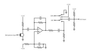
We allow two modes of audio input: 1) Microphone, and 2) Auxiliary Input via 3.5mm Audio Jack (AUX). Each mode has a corresponding circuit and state input, which are selected by a DPDT slide switch (though we used two SPDT switches for the same effect).
The microphone circuit uses an electret microphone to generate the input signal, which then goes through a pre-amplifier stage to bring the signal up to line level.
The AUX circuit is a basic RC high-pass filter with an added DC bias on the input to minimize clipping. Since the AUX input is already at line level, no amplification is needed.
Hardware+Software Co-Design
A prevalent theme of the course was letting hardware do what hardware is good at and software do what software is good at. In this way, you can offload computationally heavy tasks to hardware and free up CPU cycles to do other things. We integrated this concept into our project through the use of the Direct Memory Access (DMA) hardware peripheral on the PIC. The DMA channel was set up to work with the ADC.
We first set up a hardware timer to trigger the ADC to sample the audio signal. We then utilized DMA to move these samples into a 256 space “sample” array. When this array was filled, we performed FFT on the data in this array and began the process again.
Moving the data from the ADC to the array that stores the sample is done by the DMA channel which exists outside of the CPU. So instead of using the CPU to read data from the ADC and write it to the sample array, we were able to use it to do other tasks like animation while the DMA channel was performing the necessary data transfer concurrently.
This is a great example of hardware+software co-design, and we will take these principles forward with us as engineers.
Results of the Design
The video above is a good representation of our final system. We were very pleased with how our system turned out. The boids move well to the beat as they respond to changes in energy within their bands. Music really made the boids come alive and led to some cool emergent behaviors which was an outcome we hoped for from the beginning. This project was largely a computer graphics project and, like Professor Adams said, if it looks right, it is right, and our system looks right. It responded in real time to music and did not flicker. We sought to make something that would be fun to play with, and we certainly had fun playing with it.
Conclusions
Even though we were very pleased with our results, we acknowledge there are a number of optimizations that we could implement to speed up our system even further. We could have optimized Boid’s Algorithm. We could have found ways to offload more CPU cycles by using more hardware peripherals. However, once we achieved performance that we were happy with, we switched our focus to trying to implement cool behaviors for the boids.
Another improvement we talked about was having the system normalize noise levels somehow. The system had to be tuned to the lab environment, but in its current state, it would be useless in a very noisy environment if it was in microphone mode. This is because the energy level of all 3 bands would likely never fall below the threshold, and it is the crossing of the threshold that leads to the interesting behaviors. One benefit of having the audio jack mode is that its performance does not depend on the environment when it is operating in this mode.
Thus the audio jack mode would likely be an important feature for any commercial use of this product. One use we have discussed is integrating this product into an amplifier. In this way you could play your electric guitar and have the boids dance to your music. Another potential use for this system is at concerts. Our system could produce a cool graphic to display on the big screen behind the artist or band.
This product is also potentially especially valuable to the deaf community. Allowing deaf people to visualize music might be something that they find inspiring or moving in some way.
We think that this product would be entertaining to play with at a music store or festival as well. Because this system seems unique, there is a possibility that we could patent it, but we do not know for sure.
We certainly enjoyed making this project, and we hope you enjoyed learning about it!
Appendix A: Permissions
The group approves this report for inclusion on the course website. The group approves the video for inclusion on the course youtube channel.
Appendix B: Source Code
/*
 * File:   dancingboids.c
 * Author: bjw87, ac2338, msm296
 *
 * Created on December 3, 2021, 12:58 PM
 */

/**
 * This is a very small example that shows how to use
 * === OUTPUT COMPARE and INPUT CAPTURE ===
 * The system uses hardware to generate precisely timed
 * pulses, then uses input capture to compare the capture period
 * to the generation period for accuracy
 *
 * There is a capture time print-summary thread
 * There is a one second timer tick thread
 *
 * On the SECABB:
 * -- Pin RB5 and RB9 are output compare outputs
 * -- Pin RB13 is input capture input -- connect this to one of the output compares
 *
 * Modified by Bruce Land
 * Jan 2018
 */
//lattice high centering factor high avoiding and protected range high too

////////////////////////////////////
// clock AND protoThreads configure!
// You MUST check this file!
#include "config_1_3_2.h"
// threading library
#include "pt_cornell_1_3_2.h"

////////////////////////////////////
// graphics libraries
#include "tft_master.h"
#include "tft_gfx.h"
// need for rand function
#include <stdlib.h>
#include <math.h>
////////////////////////////////////

// === thread structures ============================================
// thread control structs

// note that UART input and output are threads
static struct pt pt_print, pt_time ; //, pt_input, pt_output, pt_DMA_output ;
// system 1 second interval tick
int sys_time_seconds ;
// string buffer
char buffer[60];

// FFT
#define begin {
#define end }
#define N_WAVE          256
#define LOG2_N_WAVE     8
#define float2Accum(a) ((_Accum)(a))
#define Accum2float(a) ((float)(a))
#define int2Accum(a) ((_Accum)(a))
#define Accum2int(a) ((int)(a))
#define nSamp 256
volatile _Accum Sinewave[N_WAVE];
volatile _Accum window[N_WAVE];
_Accum fr[N_WAVE];
_Accum fi[N_WAVE];
_Accum sample[nSamp] ;

volatile int latticeFormation[3]; //each spot is for a group... 1 represents that group should be in lattice foramtion 0 represents boid formation
volatile _Accum magSums[3];

void FFTfix(_Accum fr[], _Accum fi[], int m)
begin
    int mr,nn,i,j,L,k,istep, n;
    _Accum qr,qi,tr,ti,wr,wi;

    mr = 0;
    n = 1<<m;   //number of points
    nn = n - 1;

    /* decimation in time - re-order data */
    for(m=1; m<=nn; ++m)
    begin
        L = n;
        do L >>= 1; while(mr+L > nn);
        mr = (mr & (L-1)) + L;
        if(mr <= m) continue;
        tr = fr[m];
        fr[m] = fr[mr];
        fr[mr] = tr;
        //ti = fi[m];   //for real inputs, don't need this
        //fi[m] = fi[mr];
        //fi[mr] = ti;
    end

    L = 1;
    k = LOG2_N_WAVE-1;
    while(L < n)
    begin
        istep = L << 1;
        for(m=0; m<L; ++m)
        begin
            j = m << k;
            wr =  Sinewave[j+N_WAVE/4];
            wi = -Sinewave[j];
            //wr >>= 1; do need if scale table
            //wi >>= 1;

            for(i=m; i<n; i+=istep)
            begin
                j = i + L;
                tr = (wr*fr[j]) - (wi*fi[j]);
                ti = (wr*fi[j]) + (wi*fr[j]);
                qr = fr[i] >> 1;
                qi = fi[i] >> 1;
                fr[j] = qr - tr;
                fi[j] = qi - ti;
                fr[i] = qr + tr;
                fi[i] = qi + ti;
            end
        end
        --k;
        L = istep;
    end
end


// FFT Thread
#define CHN_BUSY 0x80
#define log_min 0x10
#define myabs(a) ((a>0)?a:-a)
_Accum alpha = 0.960433870103;
_Accum beta = 0.397824734759;
_Accum mag[N_WAVE];
int max_amp_index = 2;
_Accum magSum = 0;
_Accum firstBandMag = 0;
_Accum secondBandMag = 0;
_Accum thirdBandMag = 0;
int freqColor;
volatile int mode = 0;
static PT_THREAD (protothread_fft(struct pt *pt)){

    // Freq Bins
    // Bass = 87.31 - 349.23
    // Baritone = 98 - 392
    // Tenor = 130 - 493.88
    // Contralto = 130.81 - 698.46
    // Soprano = 246.94 - 1174.40
    mPORTBSetPinsDigitalIn(BIT_7);
    PT_BEGIN(pt);
    static int sample_number ;
    while(1) {
        // yield time 1 second
        PT_YIELD_TIME_msec(30);

        // enable ADC DMA channel and get
        // 64 samples from ADC
        DmaChnEnable(0);
        // yield until DMA done: while((DCH0CON & Chn_busy) ){};
        PT_WAIT_WHILE(pt, DCH0CON & CHN_BUSY);
        //
        // profile fft time
        WriteTimer4(0);
        // compute and display fft
        // load input array
        magSum = 0;
        firstBandMag = 0;
        secondBandMag = 0;
        thirdBandMag = 0;
        for (sample_number=0; sample_number<nSamp-1; sample_number++){
            // window the input and perhaps scale it
            fr[sample_number] = (sample[sample_number] << 6) * window[sample_number];
            fi[sample_number] = 0;
        }

        FFTfix(fr, fi, LOG2_N_WAVE);

        for (sample_number=0; sample_number<(nSamp/2)-1; sample_number++){
            fr[sample_number] = myabs(fr[sample_number]);
            fi[sample_number] = myabs(fi[sample_number]);
            if(myabs(fr[sample_number]) >= myabs(fi[sample_number])){
                mag[sample_number] = alpha * myabs(fr[sample_number]) + beta * myabs(fi[sample_number]);
            }
            else{
                mag[sample_number] = alpha * myabs(fi[sample_number]) + beta * myabs(fr[sample_number]);
            }
//            mag[sample_number] = ((fr[sample_number]) * (fr[sample_number])) + ((fi[sample_number]) * (fi[sample_number]));
            magSum = magSum + mag[sample_number];

            if(sample_number > 1 && mag[sample_number] > mag[max_amp_index]){
                max_amp_index = sample_number;
            }

        }

        for (sample_number=5; sample_number < 43; sample_number++){
            firstBandMag = firstBandMag + mag[sample_number];
        }
        for (sample_number=43; sample_number < 85; sample_number++){
            secondBandMag = secondBandMag + mag[sample_number];
        }
        for (sample_number=85; sample_number < 128; sample_number++){
            thirdBandMag = thirdBandMag + mag[sample_number];
        }
        magSums[0]=firstBandMag;
        magSums[1]=secondBandMag;
        magSums[2]=thirdBandMag;

        mode = mPORTBReadBits(BIT_7);
        if(mode == 128){
            if (firstBandMag>3000){
                latticeFormation[0]=0;
            } else{
                latticeFormation[0]=1;
            }
            if (secondBandMag>2800){
                latticeFormation[1]=0;
            } else{
                latticeFormation[1]=1;
            }
            if (thirdBandMag>3200){
                latticeFormation[2]=0;
            } else{
                latticeFormation[2]=1;
            }
        }
        else{
            if (firstBandMag>30000){
               latticeFormation[0]=0;
           } else{
               latticeFormation[0]=1;
           }
           if (secondBandMag>28000){
               latticeFormation[1]=0;
           } else{
               latticeFormation[1]=1;
           }
           if (thirdBandMag>32000){
               latticeFormation[2]=0;
           } else{
               latticeFormation[2]=1;
           }
        }
      } // END WHILE(1)
  PT_END(pt);
}

// === Animation Thread =============================================
// update a 1 second tick counter
static _Accum xc=int2Accum(120), yc=int2Accum(160), vxc=int2Accum(0), vyc=0;
_Accum xpos_avg;
_Accum ypos_avg;
_Accum xvel_avg;
_Accum yvel_avg;
_Accum neighboring_boids;
_Accum close_dx;
_Accum close_dy;


struct boid{
    _Accum x;
    _Accum y;
    _Accum vx;
    _Accum vy;
    int group;
};

#define flockSize 15
volatile _Accum turnfactor = float2Accum(0.5);
volatile int visualRange = 200;
volatile int visualRangeSquared = 4000;
volatile int protectedRange = 200;
volatile int protectedRangeSquared = 400;
volatile _Accum centeringfactor = float2Accum(1);
volatile _Accum avoidfactor = float2Accum(1);
volatile _Accum matchingfactor = float2Accum(0.01);

//#define lattice visualRange = 200; visualRangeSquared = 4000; protectedRange = 20; protectedRangeSquared = 400; centeringfactor = float2Accum(1); avoidfactor = float2Accum(1); matchingfactor = float2Accum(0.01); maxspeed=5;


int green=0b0000011000000000;
int red=  0b1100000000000000;
int blue= 0b0000000000011000;
int greenSign=-1;
int blueSign=-1;
int redSign=-1;


volatile int colors[3];

///group 1
    ///lattice
//int visualRange = 200;
//int visualRangeSquared = 4000;
//int protectedRange = 20;
//int protectedRangeSquared = 400;
//_Accum centeringfactor = float2Accum(1);
//_Accum avoidfactor = float2Accum(1);
//_Accum matchingfactor = float2Accum(0.01);

// does this define work and is it inefficient to reassign variables every time through the loop?


int maxspeed = 3;
int minspeed = 2;
_Accum dx;
_Accum dy;
_Accum squaredDistance;
_Accum topmargin = 50;
_Accum bottommargin = 50;
_Accum leftmargin = 50;
_Accum rightmargin = 50;
_Accum speed;
unsigned int begin_time;
unsigned int end_time;
unsigned int loop_time;
unsigned int fps;
_Accum neighborDenom;

#define lattice visualRange = 200; visualRangeSquared = 4000; protectedRange = 20; protectedRangeSquared = 400; centeringfactor = float2Accum(1); avoidfactor = float2Accum(1); matchingfactor = float2Accum(0.01); maxspeed=5;
//#define lattice visualRange = 200; visualRangeSquared = 40000; protectedRange = 50; protectedRangeSquared = 2500; centeringfactor = float2Accum(1); avoidfactor = float2Accum(100); matchingfactor = float2Accum(0.01); maxspeed=5;
#define motion maxspeed=3; visualRange = 200; visualRangeSquared = 40000; protectedRange = 10; protectedRangeSquared = 100; centeringfactor = float2Accum(0.0005); avoidfactor = float2Accum(0.05); matchingfactor = float2Accum(0.05);


char new_slider = 0;
// current slider
int slider_id;
float slider_value ; // value could be large
// current string
char receive_string[64];


static PT_THREAD (protothread_anim(struct pt *pt))
{
    PT_BEGIN(pt);
    /// test lattice formation
//    latticeFormation[0]=1;
//    latticeFormation[1]=0;
//    latticeFormation[2]=1;
    //Will run once
    colors[0]=red;
    colors[0]=0b1110000000011111;
    colors[1]=green;
    colors[2]=blue;

    static struct boid boids[3*flockSize];
    int i;
    for (i=0;i<3*flockSize;i++){
        boids[i].x = (_Accum)((rand() % 141) + 50);
        boids[i].y = (_Accum)((rand() % 221) + 50);
    //Limits Velocity Range, Come back to fix
    //Convert to actual velocity instead of vectorizing
        boids[i].vx = (_Accum)((rand() / RAND_MAX) + 2);
        boids[i].vy = (_Accum)((rand() / RAND_MAX) + 2);
    }
    for (i=0;i<flockSize;i++){
        boids[i].group=0;
    }
    for (i=flockSize;i<2*flockSize;i++){
        boids[i].group=1;
    }
    for (i=2*flockSize;i<3*flockSize;i++){
        boids[i].group=2;
    }

      while(1) {
        // yield time 1 second

        begin_time = PT_GET_TIME();

//        colors[1]=(colors[1]-0b0000000000100000)&0b0000011111100000;
       if ((colors[1]>=0b0000011111100000) || (colors[1]<=0b0000000111000000)){
            greenSign=greenSign*-1;
        }
        if (greenSign==-1){
            colors[1]=(colors[1]+0b0000000000100000)&0b0000011111100000;
        } else {
            colors[1]=(colors[1]-0b0000000000100000)&0b0000011111100000;
        }

//        colors[0]=0b1111100000011111;
         if ((colors[0]>=0b1110100000011111) || (colors[0]<=0b0011100000011111)){
            redSign=redSign*-1;
        }
        if (redSign==-1){
            colors[0]=(colors[0]+0b0000100000000000)&0b1111100000000000;
        } else {
            colors[0]=(colors[0]-0b0000100000000000)&0b1111100000000000;
        }


         if ((colors[2]>=0b0000000000011101) || (colors[2]<=0b0000000000000011)){
            blueSign=blueSign*-1;
        }
        if (blueSign==-1){
            colors[2]=(colors[2]+0b0000000000000001)&0b0000000000011111;
        } else {
            colors[2]=(colors[2]-0b0000000000000001)&0b0000000000011111;
        }

        // erase disk
        static int i;
        static int j;

        for(i = 0;i < 3*flockSize;i++){
            tft_fillCircle(Accum2int(boids[i].x), Accum2int(boids[i].y), 4, ILI9340_BLACK); //x, y, radius, color
            xpos_avg=0;
            ypos_avg=0;
            xvel_avg=0;
            yvel_avg=0;
            neighboring_boids=0;
            close_dx=0;
            close_dy = 0;

            if (latticeFormation[boids[i].group]==1){
                lattice
            } else {
                motion
            }

            for(j = 0;j < 3*flockSize;j++){
                if((j != i) && boids[i].group==boids[j].group){
                    dx = boids[i].x - boids[j].x;
                    dy = boids[i].y - boids[j].y;

                    if((myabs(dx) < visualRange) && (myabs(dy) < visualRange)){
                        squaredDistance = dx * dx + dy * dy;

                        if(squaredDistance < protectedRangeSquared){
                            close_dx += boids[i].x - boids[j].x;
                            close_dy += boids[i].y - boids[j].y;
                        }

                        else if(squaredDistance < visualRangeSquared){
                            xpos_avg += boids[j].x;
                            ypos_avg += boids[j].y;
                            xvel_avg += boids[j].vx;
                            yvel_avg += boids[j].vy;

                            neighboring_boids += 1;
                        }
                    }
                }
            }

            if(neighboring_boids > 0){
                neighborDenom=((_Accum)1)/neighboring_boids;
                xpos_avg = xpos_avg*neighborDenom;
                ypos_avg = ypos_avg*neighborDenom;
                xvel_avg = xvel_avg*neighborDenom;
                yvel_avg = yvel_avg*neighborDenom;


                boids[i].vx = (boids[i].vx + (xpos_avg - boids[i].x)* centeringfactor + (xvel_avg - boids[i].vx)* matchingfactor);
                boids[i].vy = (boids[i].vy + (ypos_avg - boids[i].y)* centeringfactor + (yvel_avg - boids[i].vy)* matchingfactor);

            }


            boids[i].vx = boids[i].vx + (close_dx * avoidfactor) * ((magSums[boids[i].group]*3) >> 13);
            boids[i].vy = boids[i].vy + (close_dy * avoidfactor) * ((magSums[boids[i].group]*3) >> 13);

            if(boids[i].y > (((_Accum)269))){
                boids[i].vy = boids[i].vy - turnfactor;
            }
            if(boids[i].x > (_Accum)189){
                boids[i].vx = boids[i].vx - turnfactor;
            }
            if(boids[i].x < (leftmargin)){
                boids[i].vx = boids[i].vx + turnfactor;
            }
            if(boids[i].y < (topmargin)){
                boids[i].vy = boids[i].vy + turnfactor;
            }

            //Slow step! Lookup the "alpha max plus beta min" algorithm
            if(myabs(boids[i].vx) >= myabs(boids[i].vy)){
                speed = alpha * myabs(boids[i].vx) + beta * myabs(boids[i].vy);
            }
            else{
                speed = alpha * myabs(boids[i].vy) + beta * myabs(boids[i].vx);
            }//Calculate the boid's speed

            //need to normalize by speed so we will still need speed here should probably go back to alpha max beta min
            //speed = sqrt((boids[i].vx*boids[i].vx + boids[i].vy*boids[i].vy));
            // do denominator = ((_Accum)1)/speed
            //Enforce min and max speeds
            if(speed < (minspeed)){
                boids[i].vx = (boids[i].vx/speed)*minspeed;
                boids[i].vy = (boids[i].vy/speed)*minspeed;
            }

            if(speed > (maxspeed)){
                boids[i].vx = (boids[i].vx/speed)*maxspeed;
                boids[i].vy = (boids[i].vy/speed)*maxspeed;
            }

            //Update boid's position
            boids[i].x = boids[i].x + boids[i].vx;
            boids[i].y = boids[i].y + boids[i].vy;


            tft_fillCircle(Accum2int(boids[i].x), Accum2int(boids[i].y), 4, colors[boids[i].group]);

//            tft_fillCircle(Accum2int(boids[i].x), Accum2int(boids[i].y), 4, ILI9340_GREEN); //x, y, radius, color
          //  tft_fillCircle(Accum2int(boids[i].x), Accum2int(boids[i].y), 4, freqColor); //x, y, radius, color
        }
        end_time = PT_GET_TIME();
        PT_YIELD_TIME_msec(32-(end_time-begin_time));//will need to make this smaller as boids get bigger


       //tft_fillCircle(Accum2int(xc), Accum2int(yc), 4, ILI9340_GREEN); //x, y, radius, color
        // NEVER exit while
      } // END WHILE(1)
  PT_END(pt);
} // animation thread


static PT_THREAD (protothread_timer(struct pt *pt))
{
    PT_BEGIN(pt);
    static int cursory;
    static char periodbuffer[128];
    static int start=0;

    while(1) {
        // yield time 1 second
        PT_YIELD_TIME_msec(1000) ;
//        cursory=0;
//        int i;
//        for (i=0;i<10;i++){
//             tft_setCursor(0, cursory);
//            tft_fillRoundRect(0,cursory, 200, 20, 1, ILI9340_BLACK);// x,y,w,h,radius,color
//        // print the periods
//            sprintf(periodbuffer,"%f", Accum2float(mag[i+start]));
//            tft_writeString(periodbuffer);
//            cursory=cursory+20;
//
//        }
        ///print title
        tft_setTextColor(0b11111000100111111);  tft_setTextSize(2);
        tft_setCursor(60, 10);
    // print the periods
        sprintf(periodbuffer,"DANCING BOIDS");
        tft_writeString(periodbuffer);
        tft_setTextColor(ILI9340_WHITE);  tft_setTextSize(2);

//        tft_setCursor(0, 10);
//        tft_fillRoundRect(0,10, 50, 20, 1, ILI9340_BLACK);// x,y,w,h,radius,color
//    // print the periods
//        sprintf(periodbuffer,"%d", (mode));
//        tft_writeString(periodbuffer);
//
//        tft_setCursor(0, 30);
//        tft_fillRoundRect(0,30, 200, 20, 1, ILI9340_BLACK);// x,y,w,h,radius,color
//    // print the periods
//        sprintf(periodbuffer,"%u", (Accum2int(firstBandMag)));
//        tft_writeString(periodbuffer);
//
//        tft_setCursor(0, 50);
//        tft_fillRoundRect(0,50, 200, 20, 1, ILI9340_BLACK);// x,y,w,h,radius,color
//    // print the periods
//        sprintf(periodbuffer,"%u", (Accum2int(secondBandMag)));
//        tft_writeString(periodbuffer);
//
//        tft_setCursor(0, 70);
//        tft_fillRoundRect(0,70, 200, 20, 1, ILI9340_BLACK);// x,y,w,h,radius,color
//    // print the periods
//        sprintf(periodbuffer,"%u", (Accum2int(thirdBandMag)));
//        tft_writeString(periodbuffer);
//
        if(mode==128){
            tft_setTextColor(0b11111000100111111);  tft_setTextSize(2);
            tft_setCursor(0, 30);
        tft_fillRoundRect(0,30, 200, 20, 1, ILI9340_BLACK);// x,y,w,h,radius,color
    // print the periods
        sprintf(periodbuffer,"Mic Mode");
        tft_writeString(periodbuffer);
        } else{
            tft_setTextColor(0b11111000100111111);  tft_setTextSize(2);
            tft_setCursor(0, 30);
        tft_fillRoundRect(0,30, 200, 20, 1, ILI9340_BLACK);// x,y,w,h,radius,color
    // print the periods
        sprintf(periodbuffer,"AUX Mode");
        tft_writeString(periodbuffer);
        }

      }
    PT_END(pt);
}


// === Main  ======================================================

int main(void)
{

    ANSELA = 0; ANSELB = 0;
     // === config threads ==========
    // turns OFF UART support and debugger pin, unless defines are set
    PT_setup();

    // === setup system wide interrupts  ========
    INTEnableSystemMultiVectoredInt();

    // the ADC ///////////////////////////////////////

    // timer 3 setup for adc trigger  ==============================================
    // Set up timer3 on,  no interrupts, internal clock, prescalar 1, compare-value
    // This timer generates the time base for each ADC sample.
    // works at ??? Hz
    #define sample_rate 10000
    // 40 MHz PB clock rate
    #define timer_match 40000000/sample_rate
    OpenTimer3(T3_ON | T3_SOURCE_INT | T3_PS_1_1, timer_match);

    //=== DMA Channel 0 transfer ADC data to array v_in ================================
    // Open DMA Chan1 for later use sending video to TV
    #define DMAchan0 0
    DmaChnOpen(DMAchan0, 0, DMA_OPEN_DEFAULT);
    DmaChnSetTxfer(DMAchan0, (void*)&ADC1BUF0, (void*)sample, 2, nSamp*2, 2); //64 16-bit integers
    DmaChnSetEventControl(DMAchan0, DMA_EV_START_IRQ(28)); // 28 is ADC done
    // ==============================================================================

    // configure and enable the ADC
    CloseADC10(); // ensure the ADC is off before setting the configuration

    // define setup parameters for OpenADC10
    // Turn module on | ouput in integer | trigger mode auto | enable autosample
    // ADC_CLK_AUTO -- Internal counter ends sampling and starts conversion (Auto convert)
    // ADC_AUTO_SAMPLING_ON -- Sampling begins immediately after last conversion completes; SAMP bit is automatically set
    // ADC_AUTO_SAMPLING_OFF -- Sampling begins with AcquireADC10();
    #define PARAM1  ADC_FORMAT_INTG16 | ADC_CLK_TMR | ADC_AUTO_SAMPLING_ON //

    // define setup parameters for OpenADC10
    // ADC ref external  | disable offset test | disable scan mode | do 1 sample | use single buf | alternate mode off
    #define PARAM2  ADC_VREF_AVDD_AVSS | ADC_OFFSET_CAL_DISABLE | ADC_SCAN_OFF | ADC_SAMPLES_PER_INT_1 | ADC_ALT_BUF_OFF | ADC_ALT_INPUT_OFF
    //
    // Define setup parameters for OpenADC10
    // for a 40 MHz PB clock rate
    // use peripherial bus clock | set sample time | set ADC clock divider
    // ADC_CONV_CLK_Tcy should work at 40 MHz.
    // ADC_SAMPLE_TIME_6 seems to work with a source resistance < 1kohm
    #define PARAM3 ADC_CONV_CLK_PB | ADC_SAMPLE_TIME_6 | ADC_CONV_CLK_Tcy //ADC_SAMPLE_TIME_5| ADC_CONV_CLK_Tcy2

    // define setup parameters for OpenADC10
    // set AN11 and  as analog inputs
    #define PARAM4  ENABLE_AN11_ANA // pin 24

    // define setup parameters for OpenADC10
    // do not assign channels to scan
    #define PARAM5  SKIP_SCAN_ALL

    // use ground as neg ref for A | use AN11 for input A
    // configure to sample AN11
    SetChanADC10(ADC_CH0_NEG_SAMPLEA_NVREF | ADC_CH0_POS_SAMPLEA_AN11); // configure to sample AN4
    OpenADC10(PARAM1, PARAM2, PARAM3, PARAM4, PARAM5); // configure ADC using the parameters defined above

    EnableADC10(); // Enable the ADC
    ///////////////////////////////////////////////////////

    // timer 4 setup for profiling code ===========================================
    // Set up timer2 on,  interrupts, internal clock, prescalar 1, compare-value
    // This timer generates the time base for each horizontal video line
    OpenTimer4(T4_ON | T4_SOURCE_INT | T4_PS_1_8, 0xffff);

  // setup sinewave and window
    int i;
    for (i = 0; i < N_WAVE; i++) {
        Sinewave[i] = float2Accum(sin(6.283 * ((float) i) / N_WAVE)*0.5);
        window[i] = float2Accum(1.0 * (1.0 - cos(6.283 * ((float) i) / (N_WAVE - 1))));
        //window[ii] = float2fix(1.0) ;
    }

        // init the display
    tft_init_hw();
    tft_begin();
    tft_fillScreen(ILI9340_BLACK);
    //240x320 vertical display
    tft_setRotation(0); // Use tft_setRotation(1) for 320x240

    static char periodbuffer[128];
    tft_setTextColor(ILI9340_WHITE);  tft_setTextSize(2);
//    tft_setCursor(0, 100);    // print the periods
//    sprintf(periodbuffer,"fuck me %d ", N_WAVE);
//    tft_writeString(periodbuffer);

  ///////////////////////////////////////////////////////

  pt_add(protothread_fft, 1);
  pt_add(protothread_anim, 1);
  pt_add(protothread_timer, 1);

  // === initalize the scheduler ====================
  PT_INIT(&pt_sched) ;
  // >>> CHOOSE the scheduler method: <<<
  // (1)
  // SCHED_ROUND_ROBIN just cycles thru all defined threads
  //pt_sched_method = SCHED_ROUND_ROBIN ;

  // (2)
  // SCHED_RATE executes some threads more often then others
  // -- rate=0 fastest, rate=1 half, rate=2 quarter, rate=3 eighth, rate=4 sixteenth,
  // -- rate=5 or greater DISABLE thread!
  // pt_sched_method = SCHED_RATE ;

  pt_sched_method = SCHED_ROUND_ROBIN ;

  // === scheduler thread =======================
  // scheduler never exits
  PT_SCHEDULE(protothread_sched(&pt_sched));
  // ============================================
} // main
Source: Dancing Boids
- How is audio sampled for FFT?
Audio is sampled by the PIC ADC triggered by a hardware timer and transferred into a 256-sample array via DMA. - How are frequency bands defined?
The FFT output bins are split into three bands: bins 5–42 (low), 43–84 (mid), and 85–128 (high). - Can the system use a microphone and AUX input?
Yes; two input modes are supported and selected by a DPDT slide switch (implemented with two SPDT switches). - How does the system decide lattice versus boid behavior?
For each band the summed bin magnitudes are compared to a threshold; above threshold the group uses boid behavior, below threshold it uses lattice formation. - Does the project use floating point arithmetic?
No; the code uses fixed-point arithmetic with the _Accum data type for efficiency. - What hardware features improve performance?
DMA moves ADC samples into memory without CPU intervention and timers trigger ADC sampling, freeing CPU cycles for FFT and animation. - How are boids organized internally?
Boids are structs stored in an array with fields x, y, vx, vy, and group; groups limit interaction so each boid only considers same-group boids. - How is spectral leakage addressed before FFT?
A Hann window is applied to samples before feeding them to the FFT. - How are colors and animation drawn?
Animation thread updates boid positions and draws filled circles on the TFT; group colors are stored as 16-bit integers and flash between shades. - What optimization reduced computation in magnitude calculation?
The alpha max beta min formula is used to compute magnitudes from real and imaginary FFT components to save computation.