Summary of Crossed IR Beam Camera/Flash Trigger
This article describes a DIY crossed infrared beam camera trigger that activates a camera or flash when an object interrupts two IR beams. It uses a PIC10F206 microcontroller, Sharp IS471FE optical ICs, and IR LEDs to detect targets with 2ms response time. The device offers multiple modes including continuous, pulse (1–10 Hz), and reset via long button press. Construction involves PVC pipe frames, perf boards, and colored wiring for alignment and connectivity.
Parts used in the Crossed IR Beam Camera/Flash Trigger:
- Two IR LEDs
- Two Sharp IS471FE optical ICs
- PIC10F206 microcontroller
- Relay
- Bypass capacitor
- Resistor
- PICKit2 or ICD-2 programmer
- Different colors of wire
- 3/4 inch PVC pipe
- 1/2 inch PVC pipe
- PVC elbows
- 1/2 inch thread adapters
- Perf board
- Caps for PVC fittings
- 1/4 inch brass tubing
- Heat-shrink tubing
- Pushbutton switch
- Visible LED indicator
This device will trigger a camera or flash unit to automatically take a picture when an object (target) enters a specific location. It uses two, crossed infrared light beams to detect the presence of the target and close a relay that trips the camera or flash unit. Response time is about 2 ms from detection to relay closure, so if your camera doesn’t have long shutter-lag, it will capture even fast moving targets.
The optical part of the device consists of two IR LEDs and two Sharp IS471FE optical ICs (OPICs). The optical ICs have built in LED modulators and synchronous detectors, so they won’t see light from each other’s LEDs. The outputs from the OPICs are connected to an 8 pin PIC microcontroller that handles interpreting input signals and driving the relay and a visible LED that indicates the operating mode. Though there are 11 operating modes, the controller has a very simple user-interface consisting of a pushbutton switch and an LED.
On power up if the beams are properly aligned and unbroken, the LED lights continuously for 1 second then goes dark to indicate the unit is ready to operate in the continuous mode. In that mode the relay will close and remain closed and the LED will light up as long as both IR beams are interrupted. The unit is now ready to connect to your camera.
With some targets you may want to take more than one picture when the target breaks the IR beams. I have included a basic intervalometer function in the controller to allow cameras that don’t have a built-in rapid-fire mode to take multiple pictures as long as the IR beams are interrupted. Pushing the mode select button once takes the controller out of continuous mode and puts it in pulse mode. The LED will flash one time to indicate that the relay will close 1 time per second. Some cameras are faster so pushing the button again will move up to 2 pulses per second. By repeatedly pushing the button, the speed will increase from 1 pps all the way to 10 pps, each time flashing the LED to indicate the pulse frequency. Holding the button down for 2.3 seconds resets the unit and takes you back to continuous mode. 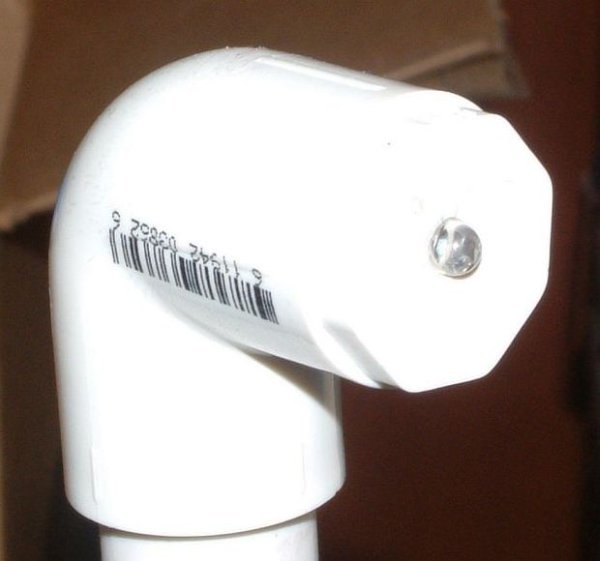
Step 1: Gather Electronic Parts
Here are the parts lists for the electronic stuff.
All of the electronics can be obtained from Digikey or other sources. You will need a bunch of different colors of wire, too.
You will need to be able to program the PIC microcontroller- a PICKit2 or ICD-2 or any of hundreds of other programmers can do the job. A suitable programmer will cost about $20, but once you have it you will find all sorts of projects that can use microcontrollers and will get a lot of use out of it.
When I bought my PICKit2 from digikey I ordered an accessory pack of five PIC10F206 chips with 8 pin DIP adapters. The IC is in a tiny SOT23 package which is fine if you’re going to make a PCB but pretty useless for breadboarding and one-off construction projects. The 10F206 is also available in an 8 pin DIP package- I suggest you use it.
I have not provided PCB layout info for the controller here because I didn’t use a PCB. The circuit is so simple that it seems sort of silly to make a PCB for it. There are only 4 parts on the board- the relay, the uC, the bypass cap, and a resistor. The circuit requires fewer parts than a 555 timer chip circuit. Just cut some perf board to fit whatever box you’re using and wire the thing up. It should take all of 30 minutes start to finish.
The optical circuits are pretty simple- an IC, a cap, and a LED. The LED and optical IC go into diagonally opposite corners of the pipe frame, so you’re going to need a bunch of colored wire. I “assembled” the IC and capacitor on small pieces of perf board that fit into cap-plugs for the PVC elbow fittings in the frame- see photos on the next page.
Step 2: The Program
I developed the program chip using MPLAB. It is Microchip Tech’s free assembler/IDE. I also used my Chinese ICD2 clone (about $50 on ebay) to actually program the IC. I needed to use a lot of delay loops so I rooted around on the web and found a program called PICLoops here:
http://www.mnsi.net/~boucher/picloops.html
PICLoops automatically generates timing loop assembly code for you if you tell it what uC you are using and the clock speed. Later on I ran into a similar on-line program here:
http://www.piclist.com/techref/piclist/codegen/delay.htm
The second one will generate delays that are accurate to a single clock cycle where PICLoops isn’t quite so accurate. Either is fine for this app because timing isn’t critical and the uC is running on an RC oscillator anyway.
The program mainly bops back and forth between checking the mode button and checking to see if the beams are interrupted. The mode switch works by keeping a running count of the number of times the button has been pressed. Each time the button is pressed the delay between the pulses to the relay gets shortened enough to step the pulse frequency by 1 Hz. The biggest part of the code is the different delays used by the pulse modes.
When you change the pulse mode the LED flashes to indicate the new mode. You can tell what the new pulse frequency is by counting the LED flashes- 4 times means 4 Hz, etc. The LED flashes have been timed slow enough that you will be able to count them. If the unit is in 10 Hz pulse mode, pushing the button again takes you back to continuous mode.
There is a watch-dog timer that runs while the program runs. If the timer isn’t reset before it overflows, the uC will reset itself. That is why holding the mode button for 2.3 seconds causes the uC to reset to continuous mode. When you push the button, the uC waits for you to release it before doing anything. One of the first things it does after you release it is reset the watch-dog timer. If you don’t release the button, the watch-dog timer overflows and restarts the program in the continuous mode.
I have attached the assembly listing file for those who are curious and the .hex file for those who just want to burn the chip and be done with it. I welcome any criticism of my programming technique from any of you PIC assembly experts out there.
Note- the relay closes for 25 ms when it operates in pulse mode. Some cameras may require a longer pulse. That delay is set in line that says “call delay25” near the top of the rlypuls section of the code. If 25 ms is too short for your camera, change that line to say “call delay50”, then change the line that says “call delay75” to say “call delay50”. That will increase the pulse time to 50 ms and still keep all the pulse frequencies at even 1 Hz steps.
The program only occupies 173 bytes out of the available 512 bytes in the chip, so you can add all sorts of functionality to the thing if you desire, though the user-interface is going to be somewhat limiting.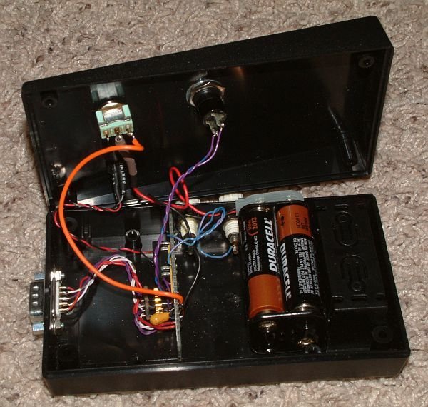
Step 3: Mechanical Construction
I initially tried to make this thing with a 3 foot square of 1/2″ pipe but found it was nearly impossible to keep the beams aligned. The distance was too great and the pipe too flexible to maintain beam alignment. I switched to 3/4″ pipe and a 2 foot square and now it all stays aligned pretty well. I used most of the 1/2″ pipe to make marshmallow blow-guns for my son, Alex, and some of his hoodlum friends.
You will need 3/4″ pipe for the main frame and 1/2″ pipe for the vertical risers that house the optical ICs and LEDs. You can get 3/4″ elbows that have a 1/2″ threaded side connection, so get some 1/2″ thread adapters too.
My philosophy about dealing with PVC pipe projects is to over-buy the fittings and pipe and return what you don’t need when the project is done. That minimizes frustrating trips to the store for a single $0.30 fitting.
You will need a bunch of different colored wire to connect all this stuff- the LEDs and their ICs are separated by about 6 feet of pipe. You will want to make the wires extra long to allow assembly and taking the thing apart for troubleshooting. Different colors will help you keep straight what connects to what.
The first thing I did was drill holes in the caps and mount the LEDs. I attached extra long wires and used heat-shrink at the LED leads to insulate them. I loosely assembled the pipe frame so I could pull it apart easily and ran the wires through the pipe.
Next, mount the IS471 chips and caps on perf board cut to fit into the opening in the end-caps. Drill a hole in the cap and install a piece of 1/4″ brass tubing (or whatever you have around). Be sure you know which side of the IS471 is the receiver side! You want it to face your LED, not the bypass cap! Attach wires to the IC board- there will be a total of five connections- Vcc, Gnd, Out, and LED. The fifth wire connects the anode of the LED to Vcc. Decide where you want to put the connector on the pipe frame and make sure the leads to the IC are long enough to reach it.
Mount the connector, run the wires, solder it all together and you’re ready to go. Don’t forget to solder a ground wire to the shell of the connector. It will help protect everything from static electricity.
Once all the wiring is done, pound the pipe together tightly with a mallet. You should not need glue, and if you glue the pipe together you’ll be unable to take it apart to fix problems later. If you want more secure construction, drive a screw through each joint after pounding them together.
When the controller is assembled you will have to align the beams. The relay will close only when BOTH IR beams are interrupted/misaligned. The outputs of the OPICs are normally low, when they can see their light source and go high when the beam is interrupted. So aligning the beams is done as follows:
1) Connect the optical frame to the controller.
2) Power on. The LED will light and stay lit unless you are extraordinarily lucky. First it lights to indicate continuous mode, then it stays lit because the beams are out of alignment. If the LED goes out it means at least one beam is aligned.
3) Assuming that the LED is lit, it indicates that both beams are misaligned. Block one beam with a piece of tape or paper.
4) Align the LED as well as you can by twisting the head to point it toward the diagonally opposite OPIC.
5) Now start flexing and twisting the OPIC head until the LED goes out, indicating that the beam is aligned.
6) Next block the freshly aligned beam, then make the same adjustments to the second beam. When the LED goes out, both beams are aligned and you’re ready to take some pictures.
Whenever you power the unit up, check the beams by blocking one then the other. If one beam is misaligned, blocking the other will cause the LED to light. Then you can just realign the one that is out of whack. If the LED lights and stays lit, both beams are out of alignment and you need to follow the procedure detailed above. If you build the thing securely and align the beams for the first time it will take some punishment before you have to do any realignments.
For more detail: Crossed IR Beam Camera/Flash Trigger
- How does the device detect a target?
It uses two crossed infrared light beams; when an object breaks both beams, a relay closes to trip the camera. - What is the response time from detection to relay closure?
The total delay is about 2 ms from the moment the beams are broken until the relay closes. - Can this device take multiple pictures automatically?
Yes, it has an intervalometer function that can pulse the relay from 1 to 10 times per second while beams are interrupted. - How do you reset the unit to continuous mode?
Holding the mode select button down for 2.3 seconds resets the unit back to continuous mode. - Which microcontroller is used in this project?
The project utilizes a PIC10F206 microcontroller running at 4 MHz. - What happens if the watch-dog timer overflows?
If the timer is not reset before overflowing, the microcontroller will reset itself to continuous mode. - How can you tell which pulse frequency is currently selected?
The visible LED flashes a specific number of times corresponding to the pulses per second, such as four flashes for 4 Hz. - Why was 3/4 inch pipe chosen over 1/2 inch for the frame?
3/4 inch pipe was used because it is less flexible than 1/2 inch pipe, making it easier to maintain beam alignment over distance.