I made this computer controlled traffic light for my work to show the status of the software being build, but I will spare you the details. This was also my first home project with a PIC controller.
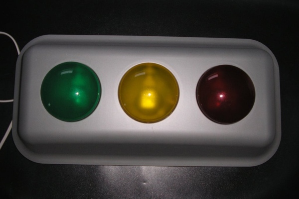
The traffic light is using an old Ikea traffic light meant for in childrens bedroom. It has switches behind each light with which you can turn on and turn of the lights. After modification, all switches and lamps are removed and the lamps are replaced by 12 Volt LED lamps. Control of the traffic light is done using a PIC controller and a – yes very old but very easy to use – RS232 serial interface. Reason for using this interface is because the PIC has it on board and it requires only an RS232 driver IC to get the interface operational. Via a simple protocol, each lamp can be individually controlled from on to off to blinking. Since the traffic light is used for representing the status of a build, the traffic light turns off automatically if it is does not receive any control updates within 10 minutes. So in order to keep the traffic light alive, the status of the lamps must be updated frequently.
This is my first Instructables post so I hope the information is sufficient to build it yourself.
Step 1: Remove the Internals and Install the LED Lamps
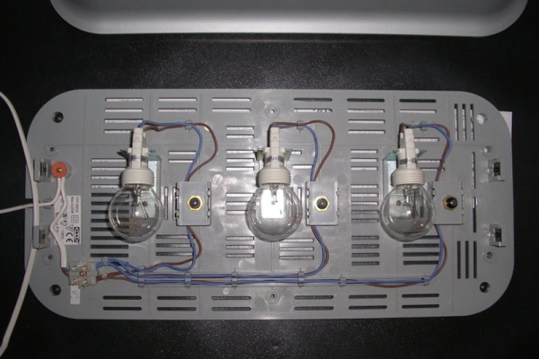
Remove all switches and the holders for the lamps. After that, install the 12 Volt LED lamps. The LED lamps are the ones that you normally use to replace 12 Volt AC halogen lamps. In our case the LED lamps are connected to 12 Volt DC which is working fine. The lamps are soldered on a breadboard which is glued to the place were intially the old lamps were mounted.
Step 2: Build the Electronics
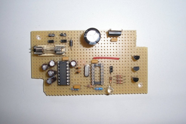
The electronics is based on a PIC 16F1823 controller and is assembled using a bread board. As power supply an external 12 Volt DC adaptor is used.
The attached Intel hex file can be used to program the PIC controller.
Since the LED lamps can be quite bright, the brightness can be lowered by removing the brightness jumpers, see the schematic diagram.
The default baudrate settings for R232 communication are 19200 baud, 8 bits no parity and one stopbit. With a jumper, the baudrate can be set to 9600 baud. The MAX232 IC is used for driving the RS232 connection.
The ‘Alive’ LED blinks with a rate of 1 Hz and shows that the traffic light is operational.
Attachments
Step 3: Mount the RS232 Connector
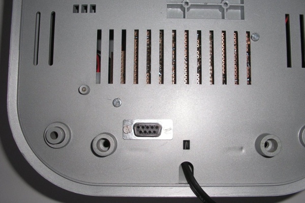
The 9 pin female RS232 D-connector is mounted on the back of the traffic light, see picture. When a connection is made to a computer, a non-twisting cable is needed.
Since RS232 is quite old and laptops do not have this interface anymore, use an USB to RS232 adapter.
Step 4: Connect It All
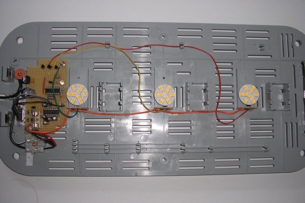
The electronics are connected to the LED lamps and the RS232 connector. The bread board can easily be mounted via some bolts but do not forget to make holes in the bread board for the bolts so that the bread board can be mounted.
Step 5: Operate the Traffic Light
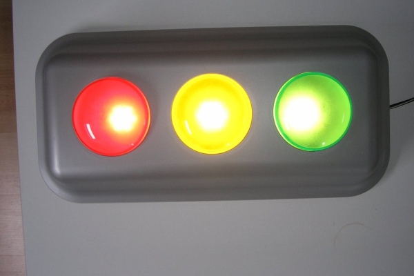
The traffic light can be tested using the protocol given in the attachment. You can use a simple terminal emulator program like ‘Termite’ to control the traffic light but you can also use the attached test program ‘Verkeerlichttest’ (sorry is in Dutch). Note that you need to have .NET installed on your computer in order to run this test program.
