
Summary of COMPUTER-CONTROLLED PROGRAMMABLE RGB LED DRIVER PIC16F628 PWM
This article describes a computer-controlled RGB LED driver project using the PIC16F628 microcontroller. It utilizes Pulse Width Modulation (PWM) to digitally simulate analog signals, allowing precise control over LED brightness and color mixing without external ballast resistors due to internal current limits. The system features a Visual Basic interface for user control, communicating with the microcontroller via an RS232 serial port (MAX232 chip), though this interface is optional for initial testing.
Parts used in the Computer-Controlled Programmable RGB LED Driver:
- PIC16F628 Microcontroller
- RGB LED
- MAX232 Chip
- RS232 Serial Port
- Visual Basic Software Interface
An interesting project computer-aided olmasıda a very good feature. Supervision can be said that the RGB PWM circuit PIC16F628 dali assembly prepared with software installed on the RGB data while sending the program’s visual basic code through a source-based… Electronics Projects, Computer-Controlled Programmable RGB LED Driver PIC16F628 PWM “led projects, microchip projects, microcontroller projects, pic16f628 projects, pwm circuits,
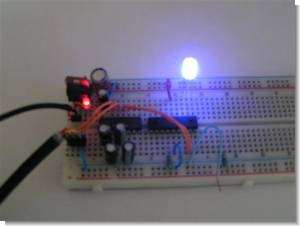
An interesting project computer-aided olmasıda a very good feature. Supervision can be said that the RGB PWM circuit PIC16F628 dali assembly prepared with software installed on the RGB data while sending the program’s visual basic code through a source-based communication used in section MAX232 RS232 serial port data is sent from the pic PIC16F628
We are going to control RGB LED with a microcontroller. Using Pulse Width Modulation (English: Pulse Width Modulation or PWM), we can digitally analog signal opwekken.Ik have used a software PWM. This is thus applicable to PIC’s with and without hardware PWM. The LEDs are connected directly to the pic outputs without ballast resistors. This is possible because the outputs are limited to a maximum of 25mA internally.
a MAX232. For a first test, this is not necessary and can be omitted initially. If one wants the colors without herprogrammerren reprogram the microcontroller then the RS232 interface is required If we connect an LED to a square wave with a 100Hz PWM of 50%, the LED will be 50% of the time and 50% off. This can people not see with the naked eye. It’s just too fast. By now setting the PWM 0n 25% LED, 25% of the time and 75%. We only see that the LED is lit. Less bright With this technique we can led to full (PWM = 100%) to completely (PWM = 0%) control.
VISUAL BASIC RGB LED DRIVER INTERFACE

Program LED color according to the codes sent over the timing of the transition period is determined transition format for burning different codes given 23 units also conducted and PWM color variants statements of the Company for the description of shared
Controlling RGB LED using a PIC 16F628. Purpose of the project: An RGB LED multi color burn. Back to the beginning. What is an RGB LED. This is basically not one but three separate LEDs LED 1 enclosure. The 3 separate LEDs have the same 3 colors as a pixel of a TV. Hence the name R ed G reen-B lukewarm. The LED that I use has 1 – connection (say RGB) a 3 + connections (say + R, and + G + B).
PIC16F628 PWM RGB LED DRIVER TEST
source: members.upc.nl Computer-Controlled Programmable RGB LED Driver PIC16F628 PWM schematic source code files alternative link
FILE DOWNLOAD LINK LIST (in TXT format): LINKS-7542.zip
Source: COMPUTER-CONTROLLED PROGRAMMABLE RGB LED DRIVER PIC16F628 PWM
-
How can we control RGB LED brightness using a microcontroller?
By using Pulse Width Modulation (PWM) to digitally generate analog signals that determine how long the LED is on versus off within a cycle. -
Do I need ballast resistors for the LEDs in this project?
No, the LEDs connect directly to the PIC outputs because the outputs are internally limited to a maximum of 25mA. -
Is the MAX232 chip required for the first test?
No, the MAX232 is not necessary for the first test and can be omitted initially if reprogramming the microcontroller is not needed. -
What happens when setting the PWM to 25%?
The LED will be lit 25% of the time and off 75% of the time, appearing dimmer to the naked eye because the flickering is too fast to see. -
Can this software PWM work on PICs without hardware PWM?
Yes, the software PWM technique described is applicable to PIC microcontrollers both with and without hardware PWM capabilities. -
What is the structure of an RGB LED in terms of connections?
An RGB LED contains three separate LEDs inside one enclosure with typically 4 connections: one common connection and three positive connections for Red, Green, and Blue. -
How does the Visual Basic interface communicate with the circuit?
The interface sends program codes through a source-based communication link using the RS232 serial port data sent from the PIC. -
What is the range of brightness control achievable with this PWM technique?
This technique allows controlling the LED from fully bright (PWM = 100%) to completely off (PWM = 0%).
