Summary of Complete Guide to Design an Advanced Line Follower Robot
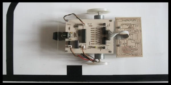
This article describes an autonomous line follower robot that tracks a black strip on a white surface using infrared sensors. The system employs eight IR transmitters and receivers to detect the path and junctions. Signals from these sensors are amplified by LM324 operational amplifiers before being processed by a PIC16F876A microcontroller. The microcontroller then controls motor directions via an L293 H-bridge motor driver, with logic determined by the reflected infrared light differences between the two surfaces.
Parts used in the Line Follower Robot:
- Infrared transmitters
- Infrared receivers
- LM324 operational amplifier
- PIC16F876A microcontroller
- L293 H-Bridge motor driver
- PCB layout components
- Schematic diagram components
Line follower is an autonomous robot which can detect a specific colored line painted on a surface of different contrast, such as white on black. In this project I used infrared transmitters and receivers to track the black strip on white surface. Due to the difference of infrared reflection on black and white surfaces, it provides two voltages which can be amplified and used as logic states.
Step 1: Electronics
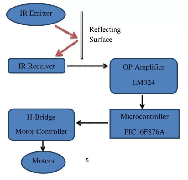
Flow chart above explains the working of the robot. There are eight IR transmitters and receivers to detect the path and junctions. Analog values from those receivers are amplified by LM324 operational amplifier. A microcontroller is used to detect the amplified digital values and to make decisions. It provides control signals to the H-Bridge motor driver (L293). More details are explained below.
Step 2: Op-Amplifier (LM324)
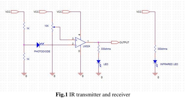
If the rays received by the IR receiver are above a particular threshold then an amplified signal is generated by the amplifier (LM324). In this project I used eight separate transmitters, receivers and amplifiers to make the tracking smooth (Fig.1) Note that the sensors cannot directly send a signal to the microcontroller as the signal voltage generated by them is too low and even when sensors are on white surfaces signal generated by them will be interpreted low by the microcontroller.
Step 3: Microcontroller(PIC16F876A)
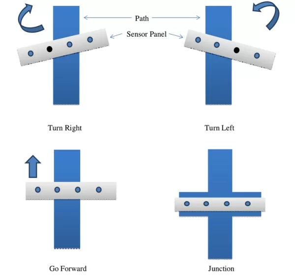
Microcontroller receives the eight amplified signals from op-amps and it decides how to control the directions of the motors as shown in Fig.
Step 4: H-bridge Motor Driver(L293)
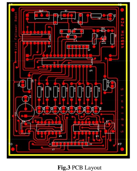
Microcontroller sends signal to the motor driver so that it can control the rotating directions. PCB layout and schematic diagram of main circuit is shown.
Step 5: Source Code – MikroC
Source Code can be downloaded from here
Source: Complete Guide to Design an Advanced Line Follower Robot
- How does the robot detect the line?
The robot uses infrared transmitters and receivers to track the black strip on a white surface based on the difference of infrared reflection. - Why are signals amplified before reaching the microcontroller?
Sensor signals are too low for the microcontroller and would be interpreted as low even on white surfaces without amplification. - What component is used to amplify the analog values?
An LM324 operational amplifier is used to amplify the analog values from the receivers. - How many IR transmitters and receivers are used in this project?
Eight separate IR transmitters and receivers are used to ensure smooth tracking and detect junctions. - Which microcontroller is utilized to make decisions?
A PIC16F876A microcontroller receives the amplified signals and decides how to control the motor directions. - What component controls the rotating directions of the motors?
The L293 H-Bridge motor driver receives signals from the microcontroller to control motor rotation directions. - Does the system work on different contrast surfaces?
Yes, the robot can detect a specific colored line painted on a surface of different contrast such as white on black. - What voltage states do the sensors provide after amplification?
The system provides two voltages which are amplified and used as logic states for decision making.