When I started building Microcontroller projects I built a lot of them using the same PIC microcontroller board. These were based on the PIC18F1320 chip since I bought a lot of them. There are many other chips in the PIC family that would be equally well suited to the projects on this site. Be aware though that, although different PIC chips program similarly, there are differences because of the varying capabilities of the chips. Also, the pins on different PIC chips don’t always have the same function.
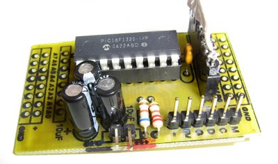
The board I created contains the following components.
- PIC18F1320 Chip
- variable voltage regulator running at 5V
- sockets for ALL external I/O connections A0-A7 and B0-B7
- connection for a PIC chip programmer
The design of the PCB board is single sided in order to simplify the board’s fabrication. I routinely make these and similar boards using the toner transfer method with good success.
When we need additional functionality, such as motor control, sensors, or communications, you can use daughter boards that connect to the main microcontroller board.
Schematics and PCBs
The basic hook up of the PIC chip is show below. On the PCB, all the I/O lines are brought out to connectors. There is a provision for a pullup resistor on the ~MCLR line. ~MCLR is normally used as a reset line. When it is pulled high (5V), the PIC runs normally. When it is pulled low (GND), the PIC chip resets. Incidentally, the ~MCLR line can also be programmed to behave as a normal I/O line in which case the pull up resistor is not required.
All the lines required to program the PIC chip are also brought out to a connector. You can use any PIC programmer using these lines but the layout is designed to mate with the Microchip PICkit 2 programmer.

In addition, there is a voltage regulator built into the board. If you plan to use a good regulated supply, you can bypass this. I use the LD1117SC-R which is a surface mount, low drop, adjustable-voltage regulator. The fact that it is surface mount allows me to place it on the reverse side of the board and save some space.
Printed Circuit Board
The PCB image below can be used to make your own PIC boards. The images, when printed, are suitable for use with the toner transfer method of PCB manufacture.
Hover over the image above and use “Save Link As” (Firefox) or “Save Target As” (MSIE) to save the full size PCB layout to your computer.
Making PCB Boards
There are various methods for the hobbyist to make PCB boards. I use the toner transfer method because it is cheap and requires relatively little setup or equipment. You need access to a laser printer or photocopier, an iron, and you’ll need an etching solution.
For more detail: Compact PIC18F1320 Microcontroller Board