Summary of X-mas Tree
This article describes a DIY Christmas tree project serving as a USB-capable development board using a PIC16F1549 microcontroller. It features PWM-driven LEDs, an ADC-controlled potentiometer for brightness adjustment, and a push button for mode switching. Designed for soldering workshops, the PCB includes both SMD components for advanced users and through-hole LEDs for beginners, with added ESD protection considerations and a 500mA fuse for safety.
Parts used in the X-mas Tree:
- PIC16F1549 µC
- N-mos drivers
- LEDs
- Potentiometer
- Push button
- SOT23-6 USB ESD protection diode array
- Serial resistors
- 500mA Fuse F1
- TSSOP IC
- SMD USB connector
- 0603 resistors
- Capacitors
As it is Christmas time and I wanted to do a simple, cheap and fun project, which works as a development board at the same time, I created this X-mas tree.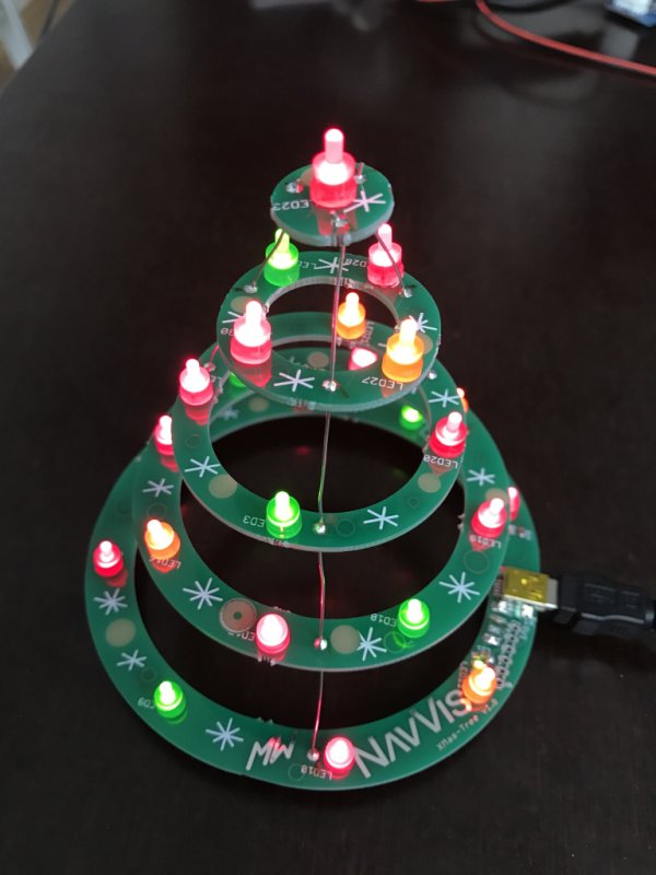
The project features an USB capable PIC16F1549 µC with:
- USB FS device
- 48 MHz internal Oscillator
- 2 PWM modules
- 10-bit ADC with Voltage Reference
- Integrated Temperature Indicator Module
The LEDs are connected to the 2 PWM outputs via N-mos drivers. A Potentiometer is connected to one ADC channel for controlling the brightness of the LEDs or possibly the speed or variation of animations. Different modes of the X-mass tree can be switched by pressing a push button.
Schematic / Layout
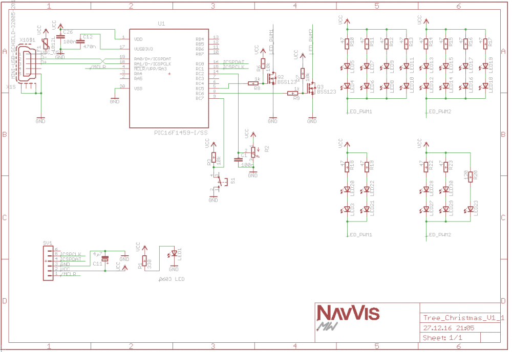
The schematic shows that the µC is directly connected to USB. This is definitely bad practice, as the µC has no ESD protection. In several other projects I used a SOT23-6 USB ESD protection diode array and sometimes two additional serial resistors.
A 500mA Fuse F1 was added to protect the PC or power supply in case of a short circuit our failure. This will be an important step, as the X-mas tree will be used for a soldering workshop for working students and anybody interested in electronics hardware or embedded software at my new job at NavVis in Munich (therefore the NavVis logo on the PCB).
The Layout is designed for two different levels of soldering skills. It features a TSSOP IC, a SMD USB connector and some 0603 resistors and capacitors for the skilled and through hole LEDs for soldering beginners.
For more detail: X-mas Tree
- What is the main function of this project?
The project works as a simple, cheap, and fun Christmas tree that also functions as a development board. - How are the LEDs controlled in this design?
The LEDs are connected to the 2 PWM outputs via N-mos drivers. - Can I adjust the brightness of the LEDs?
Yes, a Potentiometer is connected to one ADC channel for controlling the brightness or animation speed. - How do I switch between different modes?
Different modes of the X-mas tree can be switched by pressing a push button. - Why was a 500mA Fuse included?
The fuse protects the PC or power supply in case of a short circuit or failure. - Is this project suitable for beginners?
Yes, the layout features through hole LEDs specifically for soldering beginners. - Does the microcontroller have built-in ESD protection?
No, the µC has no ESD protection, which is considered bad practice in this direct connection. - What is the clock speed of the internal oscillator?
The project features a 48 MHz internal Oscillator.