
Summary of COMBINATION LOCK FOR SAFE using PIC16F628
This article details a DIY battery-powered combination lock for a Sentry fire safe using a PIC16F628 microprocessor. The system features a 6-digit keypad, an LED status indicator, and a solenoid actuator. It employs PWM to manage power consumption, delivering a high-current pulse followed by a reduced current hold phase to extend battery life. A toggle switch powers the circuit, which resets after two seconds of inactivity.
Parts used in the Combination Lock for Safe:
- PIC16F628 Microprocessor
- Solenoid (Lock Actuator)
- FET Driver
- 9V Battery
- Keypad (Keyboard with 1-9, *, 0, # keys)
- LED Indicator
- Toggle Switch
- 6MHz Crystal Oscillator
Introduction
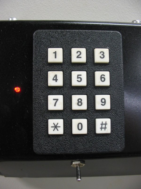
This program is a simple combination lock that I designed for an old Sentry® fire safe that was given to me without any lock electronics. I created a front panel with a keyboard and microprocessor with a six-digit combination sequence.
Details
The LED flashes to show it’s alive after power is applied.
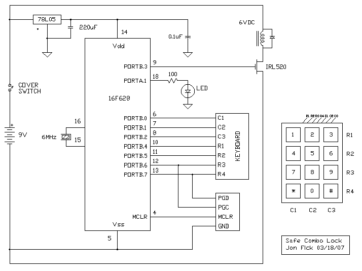
The lock solenoid requires 6VDC at approxmately 2 amps. Given that a small 9V battery is used and wouldn’t easily provide that current for very long, I used the PIC’s PWM output to vary the current in two phases:
- It starts with a 30mS “pick” phase that delivers full current by providing a 100% duty cycle to the FET driver which puts a solid 9V across the solenoid.
- That’s followed by a “hold” phase of 1.4 seconds at a reduced duty cycle that reduces current to significantly less.
The initial combination is “123456”. Regardless of any immediately prior key sequence, when that correct key sequence is entered and completed, the lock solenoid is actuated for 1.5 seconds. If a key isn’t pressed for two or more seconds, the firmware resets to again look for the first digit.
Caveats
Since this circuit is battery powered, some way is required to turn on the battery when needed. I used a toggle switch below the keypad to accomplish this, but more innovative methods would be more elegant. For instance, one could employ some sort of mechanical cover over the keypad whereby lifting the cover would actuate the switch to connect the battery.
Code:
/**************************************************************************** SAFE_COMBO_02.C PIC 16F628 Combination Lock – resets to first expected digit two seconds after last key is pressed – uses PWM to reduce current to coil after initial pulse ——— ———- +5 –14-|VCC B0|-17—–|C1 | | B1|-18—–|C2 | Gnd —5-| B2|-1——|C3 | 6MHz XTAL –16-| B4|-2——|R1 KBD | XTAL –15-| B5|-6——|R2 | | B6|-7——|R3 | | B7|-8——|R4 | | 16F628 | ———- | | | B3|-6— LOCK SOLENOID | A1|-18– LED ——— ========= | 1 2 3 | R0 | 4 5 6 | R1 | 7 8 9 | R2 | * 0 # | R3 ========= C0 C1 C2 Keyboard connector is (backside): C2 C1 C0 R3 R2 R1 R0 Oscillator = 6MHz crystal Jon Fick 03/09/07 ***************************************************************************/ #include <16F628A.h> #include // Set configuration bits in the PIC processor #fuses HS, NOPROTECT, NOWDT, PUT, BROWNOUT, NOMCLR, NOLVP #define COMBO_1 ‘1’ #define COMBO_2 ‘2’ #define COMBO_3 ‘3’ #define COMBO_4 ‘4’ #define COMBO_5 ‘5’ #define COMBO_6 ‘6’ #define KBD_C1 PIN_B0 #define KBD_C2 PIN_B1 #define KBD_C3 PIN_B2 #define KBD_R1 PIN_B4 #define KBD_R2 PIN_B5 #define KBD_R3 PIN_B6 #define KBD_R4 PIN_B7 #define LOCK_OUT PIN_B3 #define LED PIN_A1 #define NOKEY 0xFF #define RESET_KBD_COUNT 46 // at 23 counts/second #define LOCK_HIGH 255 // full PWM duty cycle #define LOCK_HIGH_TIME 30 // mS at full coil current #define LOCK_MED 20 // partial PWM duty cycle #define LOCK_MED_TIME 1450 // mS at partial coil current #define LOCK_OFF 0 // no PWM current #use delay ( clock = 6000000 ) // sets appropriate compiler constants #use standard_io ( A ) #use standard_io ( B ) char GetKey ( void ); // prototypes static char cKbdTimeoutFlag, cLedCount; #int_rtcc void TimerInterrupt ( void ) // 43mS tic, 23/second { if ( cKbdTimeoutFlag != 0 ) { cKbdTimeoutFlag–; // count down to zero } if ( cLedCount++ > 12 ) { cLedCount = 0; } if ( cLedCount > 6 ) { output_high ( LED ); } else { output_low ( LED ); } } void main ( void ) { delay_ms ( 100 ); // power up delay output_low ( LOCK_OUT ); // turn off lock solenoid */ output_low ( LED );
For more detail: COMBINATION LOCK FOR SAFE using PIC16F628
-
What is the initial combination code?
The initial combination is set to "123456". -
How does the firmware handle key input timeouts?
If a key isn't pressed for two or more seconds, the firmware resets to look for the first digit again. -
How long does the lock solenoid actuate upon entering the correct sequence?
The lock solenoid is actuated for 1.5 seconds when the correct sequence is entered and completed. -
Why is PWM used instead of direct DC for the solenoid?
A small 9V battery cannot easily provide the required 2 amps for a long time, so PWM varies the current to reduce power usage. -
What are the two phases of current delivery to the solenoid?
The process starts with a 30mS pick phase at full current (100% duty cycle) followed by a 1.4-second hold phase at reduced current. -
How is the device powered on given it is battery-operated?
A toggle switch located below the keypad is used to turn on the battery connection. -
What indicates that the system is alive after power is applied?
An LED flashes to show that the system is active. -
What oscillator frequency is used in the design?
The circuit uses a 6MHz crystal oscillator.
