Designing a DC/DC converter that only consumes micro amps of current at no load can be compared to fueling a muscle car with lighter fluid – you may get it to work, but it won’t be easy. High efficiency at full load currents is commonplace in most modern DC/DC converters; however, achieving high efficiency when the load is disabled or disconnected is still a difficult and/or expensive task.
Many automotive and industrial applications require efficient 12 V or 24 V buck power conversions from the main supply down to the point-of-load (POL) voltage at full load, but also need very low current consumption when the device is in an idle or shutdown state. In order to achieve such low current, you can easily use a Low Dropout Regulator (LDO) in parallel with a buck converter to achieve minimal current draw from the battery when the system enters a light-load/no-load state.
Ultimately, the ideal situation to prolong battery life in the system would be to disable every possible device from the input supply. In some cases though, a sub-regulated voltage is still necessary for certain components within the system to allow communication with other system blocks during the shutdown state (i.e. a CAN bus transceiver in an automotive application). DC/DC converters that are not specifically designed for light-load efficiency can consume several milliamps with no load. Additionally, converters that do exhibit high light-load efficiency will utilize frequency-foldback schemes and discontinuous mode operation, resulting in noisy output voltages and excessive EMI emissions. An LDO is ideal for light load situations because they can be designed to consume very low currents while maintaining a low noise output voltage. The no-load current into the input (also called “ground current”) can be on the order of a few micro amps or lower. Combining the performance of both converter and LDO, therefore, has obvious benefits.
A simple method of using both in parallel is possible if the designer has the ability to disable the DC/DC converter when the loads will be minimal, i.e. using the same enable/disable signal for the converter that is used for the load. An example of this can be seen in Figure 1.
Figure 1: Block diagram of DC/DC converter in parallel with LDO (Courtesy of Texas Instruments).
Figure 2 gives a generic example of an efficiency curve of a low-IQ LDO plotted with an efficiency curve of a DC/DC converter for a higher voltage conversion (i.e. 12 V to 1 V). At light loads, the LDO is more efficient. If the system spends a significant amount of time at light loads, using the LDO to regulate the voltage can drastically improve the total system efficiency.
Figure 2: Generic example of low-IQ efficiency curve (Courtesy of Texas Instruments).
Implementing the circuit in Figure 1 requires that the converter output is set at a higher voltage than the maximum LDO output voltage. In normal operation, when the converter is enabled, the converter will regulate the output voltage and provide the current to the load. Most LDOs are unable to sink current, relying on load current sourced out of the pass device to regulate the output.Pulling the output voltage of the LDO above its nominal voltage will force the LDO into an unregulated state where current will not flow from the input to the output, and the DC/DC converter will effectively operate as if the LDO was not connected.
Once the DC/DC converter is disabled, it will stop switching and the output voltage will decrease until the LDO begins to regulate the output. Upon enabling again, the DC/DC converter will start up in a pre-biased condition (a positive voltage existing on the output during startup is called “pre-biased”).The converter will begin its startup procedure without sinking any current from the output node, eventually pulling the voltage at the output above the nominal LDO voltage, and regaining control of the output.
Consider a simple battery shelf life example calculation with a 1400 mAh battery. Say a device was left in a standby state after the battery has been fully charged, and the supply connected to it was either an LDO with 10 μA quiescent current at no load or a DC/DC converter with 200 μA of quiescent current at no load.
| Battery Capacity | Battery shelf life (full initial charge) with DC/DC converter | Battery shelf life (full initial charge) with LDO |
| 1400 mAh | 1400 / 0.2 = 7000 hrs
7000 / 24 = 291.7 days |
1400 / 0.01 = 140000 hrs
140000 / 24 = 5833.3 days |
The battery life can be extended by a factor of 20x.
The discussion will now shift to how this circuit was implemented with TI devices.
The circuit in Figure 3 shows an example of efficiency improvement with an LDO in parallel with a DC/DC converter.
Figure 3: TPS709 in parallel with TPS54331 (Courtesy of Texas Instruments).
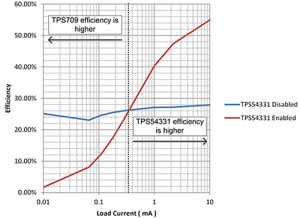
The LDO selected is the TPS709, which has a 30 V input range with only 1 µA nominal ground current. The DC/DC converter is the TPS54331, selected for its input voltage range and high efficiency. The TPS54331 already exhibits high efficiency at light loads in comparison to most comparable DC/DC converters. However, at 110 µA (typical) non-switching quiescent current, the no-load current of the converter is nearly 100 times greater than the ground current of the TPS709 at no load (1.3 µA), even before switching losses and feedback resistor loads are factored in.
Figure 4 shows the efficiency measurement differences between the TPS709 and the TPS54331. The measurement configuration is VIN = 12 V, VOUT = 3.46 V when the TPS54331 is enabled, VOUT = 3.3 V when the TPS54331 is disabled.
For more detail: How to Improve Buck Converter Light Load Efficiency with an LDO

