Summary of CD-ROM BLDC motor controller using PIC18F4550 and L293D
This project details a BLDC motor speed and direction controller using a PIC18F4550 microcontroller and two L293D motor driver chips, replacing complex 3-phase bridge circuits. The system utilizes three push buttons for start/stop control and a potentiometer on the AN0 channel to adjust motor speed. A single PWM signal from the CCP1 module is split into three signals using HEF4081BP AND gates to drive the three-phase motor windings. The microcontroller operates on its internal 8MHz oscillator.
Parts used in CD-ROM BLDC Motor Controller:
- PIC18F4550 microcontroller
- Two L293D motor driver chips
- BLDC motor (CD-ROM spindle)
- Three push buttons
- Potentiometer
- HEF4081BP IC (AND gates)
- CCP1 module
In the following topic URL we’ve seen how to control BLDC motor speed and direction of rotation using PIC18F4550 microcontroller and 3-phase bridge circuit: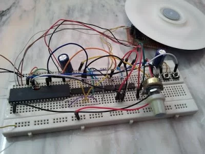 CD-ROM Spindle motor (BLDC) control with PIC18F4550 microcontroller
This topic shows how to make the same controller using L293D motor driver instead of the 3-phase bridge circuit.
The 3 phase bridge is more complicated and expansive and while the L293D motor driver chip is a small, cheap and saves time.
In this project we need two L293D chips because the BLDC motor is a three phase motor, and at any time two windings energized while the third one floating.
The L293D has 4 inputs and 4 outputs with 2 enable pins, each enable pin controls 2 outputs as shown below: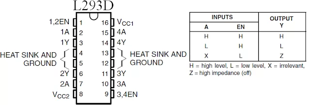 Complete circuit schematic is shown below:
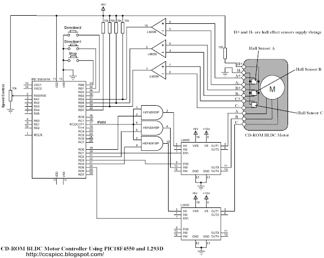
In the circuit there are 3 buttons connected to RB0, RB1 and RB2. The buttons connected to RB1 and RB2 are used to start the BLDC motor and the other button is a stop button.
The BLDC motor speed is controlled using a potentiometer connected to AN0 channel.
There are 3 AND gates (HEF4081BP) in the circuit, these gates are used to get a 3 PWM signals from the original one which comes from RC2 pin using CCP1 module.
HEF4081BP has 4 independent 2-input AND gates, three of them are used. This IC needs a supply voltage of +5V between pins 7 (GND) and 14 (VCC).
PIC18F4550 microcontroller internal oscillator is used (8MHz).
BLDC Motor control using PIC18F4550 and L293D CCS PIC C code:
For more detail: CD-ROM BLDC motor controller using PIC18F4550 and L293D
- Why are two L293D chips required?
Two chips are needed because the BLDC motor is a three phase motor requiring two windings to be energized while the third floats at any time. - How is the motor speed controlled?
The speed is controlled using a potentiometer connected to the AN0 channel. - What components are used to generate three PWM signals?
Three AND gates from an HEF4081BP IC are used to derive three PWM signals from the original signal coming from the RC2 pin. - Which microcontroller pins connect to the control buttons?
The three buttons are connected to RB0, RB1, and RB2. - What is the function of the button connected to RB0?
The button connected to RB0 acts as the stop button. - How does the circuit handle motor start and stop?
Buttons connected to RB1 and RB2 are used to start the motor, while the other button stops it. - What voltage supply is required for the HEF4081BP IC?
The IC requires a +5V supply between pins 7 (GND) and 14 (VCC). - What clock source does the microcontroller use?
The PIC18F4550 uses its internal oscillator set to 8MHz.