Summary of CARLETON PROJECTS
The Carleton Weather Station project integrates a Microchip PIC18F876-based data acquisition system with various roof-mounted sensors to monitor environmental conditions. Located in Olin 206, the setup includes humidity, temperature, wind, solar radiation, and rain gauges. The system also features an advanced instrument platform under development for tracking solar absorption and detecting lightning, alongside a radio telescope dish and a new sidereal clock within a dome.
Parts used in the Carleton Weather Station:
- Microchip PIC18F876 microcontroller
- Battery back-up unit
- Data acquisition board
- Thumb drives
- Humidity sensor
- Temperature sensor (stacked plates)
- Wind direction sensor
- Solar radiation sensor
- Wind speed anemometer
- Rain gauge with funnel and tipping bucket
- Pan-tilt platform
- Radiometer instruments
- Pyranometers
- UV radiometer
- Sky temperature sensor
- Full sky camera
- Photosynthetically Active Radiometer
- Ambient light sensor
- Barometric pressure head
- Black globe sensor
- Microphone
- Precipitation detector
- Lightning detectors
- Antenna for Lyman Lakes buoy
- Webcam
- Radio telescope dish antenna
- GPS module
- Sidereal clock
- Dome rotation mechanism
- Wireless control pendant
- Burr-Brown OPT101 photodiode/amplifier chip
- 9 volt battery
- BNC connector
- 12 mm optical filters
- Op amp amplifier box
- Charge pump converter
- Time delay relay
- 8 pin Microchip PIC microcontroller
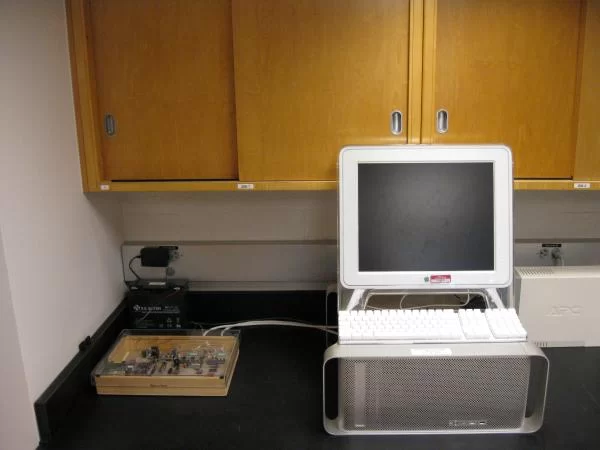
This is the Carleton Weather Station, at least the computer end of it. The data acquisition system is to the left and the web server is the Mac computer. It is located in Olin 206.
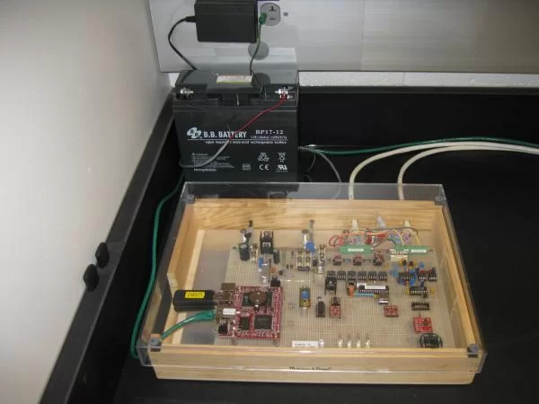
This is the Carleton Weather Station’s data acquisition system. This replaced a 1995 Mac and some daq boards. This daq system is based on a Microchip PIC18F876. It has its own battery back-up.
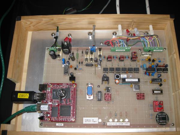
This is a more detailed picture of the Weather Station daq board. The board in the lower left interfaced with the PIC and the web server. It also stores the data in the thumb drives.
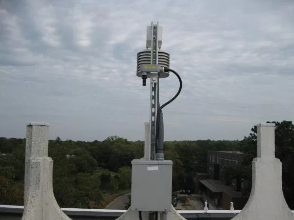
This shows two of the sensors located on the roof of Olin Hall. The black tube pointing down houses the humidity sensor. Inside the ‘stacked plates’ is the temperature sensor. The view is looking east, and in the distance you can see the Carleton wind turbine. (lower right center)
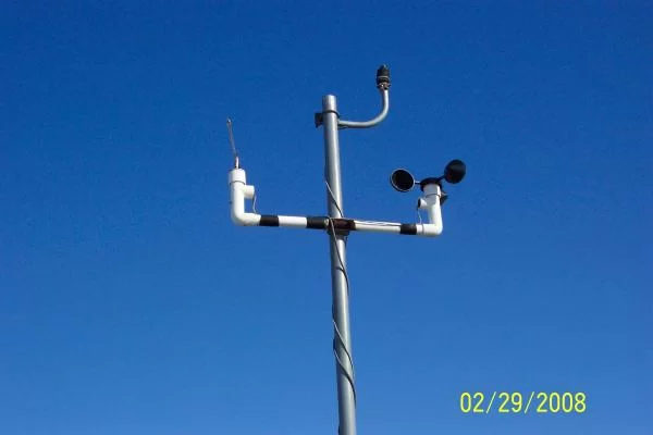
Located on this mast are the wind direction sensor (left side), solar radiation sensor (top center), and wind speed anemometer (right). These are located on the roof of Olin Hall.
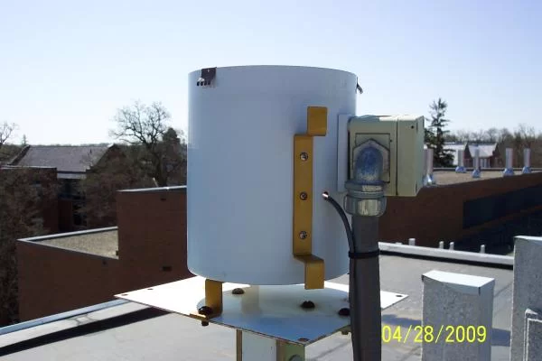
This is the rain gauge located on the roof of Olin Hall. Inside the top is a funnel which directs water collected in the 8″ opening down to the tipping bucket.
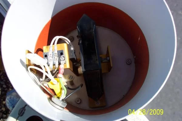
This is what the inside of the rain gauge looks like with the funnel removed. It is kind of hard to see but the black object in the middle is the tipping bucket. When one side fills with .01″ of rain it tips to the other side and sends a pulse to the data acquisition system. The daq system counts these pulses and
displays them to the nearest .01″ of rain (or melted snow in the winter).
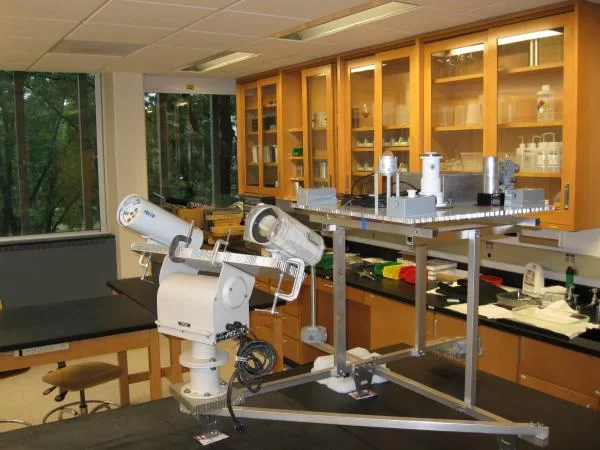
This is a new instrument platform under development to also go on the roof of Olin Hall. The left shows two radiometer instruments on a pan-tilt platform that will track the sun. The sun will be the light source and between the sun and the sensors is the atmosphere, which will be sensed at different wavelengths
to monitor its changes relating to solar absorbtion. On the platform on the top are two pyranometers, a UV radiometer, a sky temperature sensor, a full sky camera, a Photosynthetically Active Radiometer (measures the visible light spectrum used by plants), an ambient light sensor, and some special sensors.
An additional boom extends out with a special barometric pressure head that compensates for wind effects, a black globe sensor that simulates how outdoor animals might experience sunlight, a microphone to ‘hear’ thunder, and a detector that can differentiate between different types of precipitation. There are also lightning detectors that work like AM radios to detect static as well as an optical sensor that can detect the flash. Also located on this structure are precipitation sensors that will signal the first drop of rain, an antenna for the Lyman Lakes buoy, and a webcam allowing users to view
the inner part of campus.
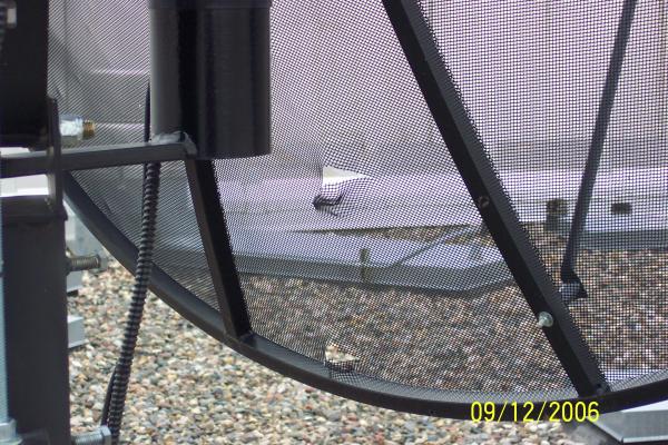
Note the two holes in the small radio telescope dish antenna located on the roof of Olin Hall.
These are the result of the recent hail storm that blew thru. The top of the dish has lots of
dimples in it also.
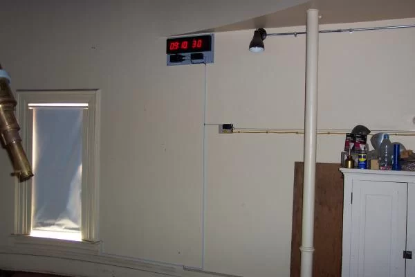
The new sidereal clock located in the 16″ dome. It gets its time from GPS and automatically dims as the dome gets darker or via wireless control.
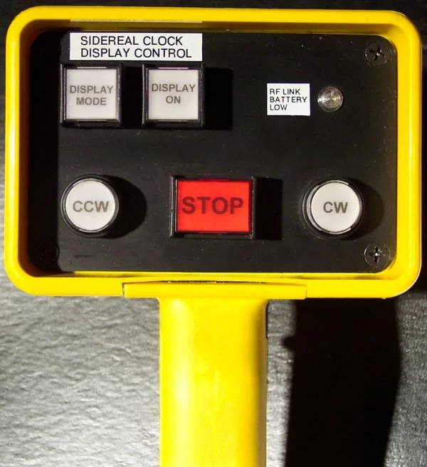
This is the wireless control pendant that allows the operator to rotate the dome clockwise or counter-clockwise and then stop its rotation. It also has buttons to control the intensity of the sidereal clock display and an indicator to notify when the RF link’s battery is low. The pendant also has the cool abiltiy to illuminate all the buttons red when it is picked up. It does this by sensing the hand’s capacitance. This allows the operator to see the buttons while working in a darkened dome.
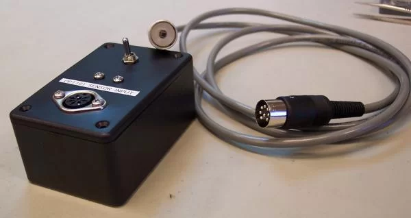
Located in the center of the aluminum cylinder is a Burr-Brown OPT101 photodiode/amplifier chip. It is powered by a 9 volt battery inside the box, and the signal is tapped off and output on a BNC connector. The cylinder accepts 12 mm optical filters such as narrow bandwidth interference types.
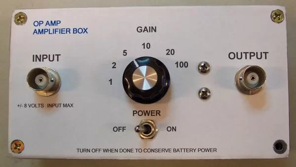
This is a handy op amp amplifier box for use in labs. It is battery powered and allows differing gains to be selected. It uses a precision op amp powered by a 9 volt battery. The negative voltage is generated by a charge pump converter. The label on the diecast aluminum box was created in Microsoft WORD and printed on a sheet of label paper and then cut to fit the top.
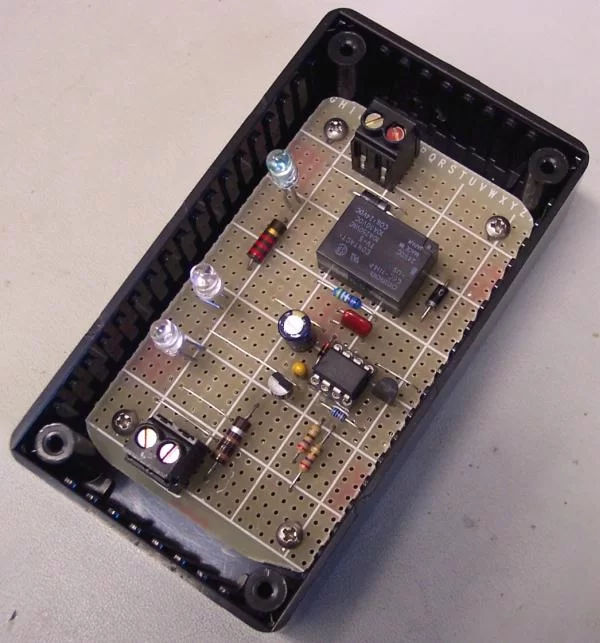
This is the guts of a time delay relay for a dc powered compressor. It uses an 8 pin Microchip
PIC microcontroller to monitor the 24 volt dc supply. If the supply goes out of range the relay
turns off. Once the power is restored at its operating specification there is a 10 minute delay
before the relay is turned back on. This gives the compressor time to equalize pressures
before trying to start again as might typically happen after a power outage.
Source: CARLETON PROJECTS
- How does the rain gauge measure precipitation?
The funnel directs water to a tipping bucket that tips every .01" of rain or melted snow to send a pulse to the data acquisition system. - What is the purpose of the pan-tilt platform on the new instrument platform?
The platform tracks the sun so sensors can monitor atmospheric changes relating to solar absorption at different wavelengths. - Does the wireless control pendant work in the dark?
Yes, it illuminates all buttons red when picked up by sensing the hand's capacitance to allow visibility in a darkened dome. - What powers the Burr-Brown OPT101 photodiode/amplifier chip?
The chip is powered by a 9 volt battery located inside the aluminum cylinder. - How does the time delay relay protect the compressor?
It enforces a 10 minute delay after power restoration before turning the relay back on to allow pressures to equalize. - Can the sidereal clock adjust its brightness automatically?
Yes, it dims automatically as the dome gets darker or via wireless control. - What types of sensors are located on the mast on the roof of Olin Hall?
The mast holds the wind direction sensor, solar radiation sensor, and wind speed anemometer. - How does the system detect different types of precipitation?
Special sensors on the new platform differentiate between different types of precipitation.