Summary of Car battery charger with PIC12F683
This article details the design and assembly of a custom 12V car battery charger for a countryside home lacking grid power. The author replaced a broken old charger using a PIC12F683 microcontroller to manage charging logic, indicator LEDs, and relay control. The project involves modifying an enclosure to house components like a transformer, voltage regulator, and panel meter, ensuring safe and automated battery maintenance.
Parts used in the Car Battery Charger with PIC12F683:
- Enclosure
- Transformer
- Panel meter
- Banana-plugs and sockets
- 220V cable socket
- Fuse holder
- Button
- LED (green and red)
- PIC12F683 microcontroller
- 220ohm resistors
- 4K7 resistor
- 1K resistor
- Voltage divider resistors
- LM7805 voltage regulator
- PicKit2 or PicKit3 programmer
- Wire terminal block
- NPN transistor
- Relay
- Screws
- Hand tools (drills, saw, sand paper)
- Computer
- Extension chord
This time I’m starting off with a device I already built, unfortunately there won’t be any photos from the actual build, just a quick article on how I imagined it and how it works.
A short story about how the whole thing started
My uncle has a nice little place at the countryside at about 50 kilometers away from where we live. Unfortunately there is no electricity in the house, so the lights, music, and anything else that’s electronic runs from a 12V car battery. The battery was charged before each trip with an old-school car battery charger, until the charger eventually broke. He brought it to me to get it repaired, but the two components it had inside both were dying so I decided to build him a new one. His birthday was coming, so I decided to make it as a present. I haven’t finished building it on time, but he was all-right with it!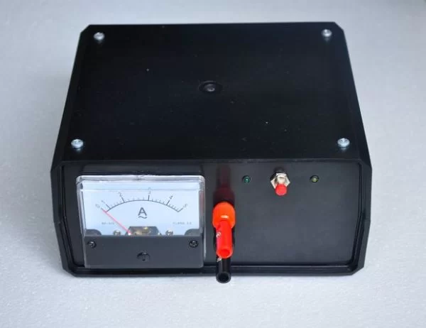
Step 1: Parts list
Here’s a list of the thing you will need to make a copy:
- Enclosure – buy the one you like the most, or make your own
- Transformer – think of the charging current, then make your decision about the amps. I have this one.
- Panel meter – must be able to measure your transformers maximum current. I have this one.
- Banana-plugs and sockets – buy in bulk off ebay.
- 220V cable socket – I bought this one.
- Fuse holder – I bought this one, this is for the transformers secondary winding
- Button – a random button, I’ve had this for ages
- LED – buy in bulk off ebay, I used a green and a red one, both 3 mm
- PIC12F683 – ebay link, buy more of these, they’re very useful for small MCU projects
- 220ohm resistors – protection resistors for the LEDs
- 4K7 resistor – pull-up resistor for the button input
- 1K resistor – series protection resistor for the NPN transistors base pin
- Voltage divider resistors – any kind of resistors with 1:4 dividing ratio
- LM7805 – TO220 voltage regulator, buy in bulk off ebay
- PicKit2 or PicKit3 – build or buy, I used my home-made PicKit2 for the job
- Wire terminal block – I used this kind of connectors
- NPN transistor – a random BC transistor that is able to handle 30 mA
- Relay – general purpose small relay, able to handle the charging current
- Screws – 4 mm screws for the transformer
- Drills, saw, sand paper and other hand tools
- Computer to write the firmware on.
- Extension chord for mains
Step 2: The enclosure
First, you need to imagine what the charger should look like, and get an enclosure that can fit in all the stuff you want. At first, I ordered one I thought was good, but when I saw it with my own eyes, I almost had a heart attack. Luckily the seller had this black enclosure on stock, I bought it without further hesitation. You can see how the two enclosures look like on the photo.
When you have both the enclosure and the clue how you want it to look like, you can start fitting in the components. I used my Bionic hand drill to drill a contour of the shapes I wanted to cut out, and snapped out the pieces of plastic. A small saw and sand paper was used to give the holes and slots their final form. After I cut these slots, I snapped in the components that supposed to go on the front and the back panels. The arrangement of components in and on the enclosure:
- Front panel: panel amp-meter, banana sockets, two LEDs and a button
- Back panel: 220V entry plug with fuses, fuse holder (for the transformers secondary winding), radiator and a current regulator (I changed my mind about this later on, but the holes were already there..)
- Inside: transformer, prototype board, electronic circuitry
Step 3: The electronics
At first I wanted to make this an analog-only schematic, but later gave up on the idea. I’ve decided to use a small PIC12F683 I’ve had on stock anyway. I was already familiar with this processor, I used it as a control unit in many of my projects, including the One-wire lock. This time I needed two LED outputs, a relay-driving-transistor output, and a button input, so the pin count proved to be more than appropriate.
When driving LEDs from a power source, current limiting resistors need to be added for the protection of LEDs. The LEDs are driven from the PIC (a 5V source), the LED forward voltage is around 2V, and we want a current of 15mA to pass through the LED. That results in a resistor of R = 5 – 2 / 0.015 = 200 ohm. I picked the closest standard value, a 220 ohm resistor.
The relay is an RS-5 relay said to have a coil current of ~30mA. That current can be handled easily by a BC transistor in TO-92 package, I chose BC546. A base-current limiting resistor of 1Kohm was used to protect the transistor, at 5V that means a 5mA base-current. The base current is in strict relation with the collector current. Instead of looking at the amplifying capability of that transistor, I chose the resistor based on an old habit: “collector current is ten times the base current”. 50mA is more than enough to drive the RS-5 relay on and off.
- Why did the author decide to build a new charger?
The original charger broke because both internal components were dying. - What microcontroller was chosen for the project?
The author selected the PIC12F683 due to familiarity and appropriate pin count. - How are the LED current limiting resistors calculated?
A 220 ohm resistor is used based on a 5V source, 2V forward voltage, and 15mA target current. - Which transistor model drives the relay in this circuit?
A BC546 NPN transistor in TO-92 package handles the ~30mA coil current. - What is the purpose of the 1K resistor connected to the transistor base?
It acts as a base-current limiting resistor to protect the transistor. - Where is the fuse holder placed in the enclosure?
It is located on the back panel for the transformers secondary winding. - What tools were used to modify the plastic enclosure?
The author used a Bionic hand drill, a small saw, and sand paper. - Can the user choose their own enclosure for this project?
Yes, the article states you can buy one you like or make your own.