
Summary of Building a SmartWatch Part 1
This article details the author's initiative to build a custom smartwatch, driven by dissatisfaction with current market trends that prioritize fashion over function. The project involves designing and prototyping electronics using DesignSpark software and a Stellaris Breakout Board. The first prototype featured an OLED display, SD card, joystick button combo, and power supply but failed due to a missing logic line and incorrect footprint, requiring adjustments before further development.
Parts used in Building a SmartWatch:
- Stellaris Breakout Board
- OLED Display (Color screen with SPI interface)
- SD Card
- Joystick Button Combo
- Power Supply for the OLED Display
- Logic High Line (for OLED driver chip)
- PCB manufactured at Seeed Studios
I have an issue with smart-watches. Watches in general fall into one of two categories: a tool to tell the time, or a fashion statement. Increasingly, I believe the latter category is larger than the first. With the advent of the iWatch, Pebble and the like, fashion and making a statement has moved into technology. It’s not quite a new thing but nevertheless, it’s something I’m not too fond of. My solution? Make your own smartwatch.
There is a precedent for this. Steve Wozniack sports a pretty fly nixie tube watch. It’s pretty cool, but also a statement of sorts too. I believe there is quite an underground scene of custom electronics watches. I’ve been meaning to up my game with electronics anyway, so I’ve been working on a few initial prototypes.
I use DesignSpark on the recommendation of a sparky friend of mine who has a successful business building bespoke electronics. I have a Stellaris Breakout Board – the same board used in the cubesats – that I figure I can use for development. Most of the parts I’ve ordered from R.S Components though that might change in the future. I’ve previously used EAGLE, which I’d also recommend.
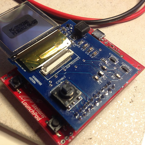
I decided the first stage would be to build a breakout-board with the easy components attached. This includes a display, an SD Card, a small joystick button combo and a power supply for the OLED display. I’ve decided to go with a colour screen, the same used in the tricorder project, as it’s fairly cheap and works with an SPI interface. The SD card also has a straight forward interface, so I figured the only tricky part was the power supply.
The first board was a little large and sadly, didn’t work. I’d missed out a logic high line into the OLED driver chip. These boards I had made at seeed studios who you may remember I tried to visit on our recent trip across Russia and China. Sadly, the day we turned up in Shenzen was a Chinese public holiday. Oh well. The eagle-eyed amongst you will notice the wire I’ve hastily added in order to test whether or not I could save the board. Apparently not. In addition, the footprint for the SD Card reader wasn’t quite right, so that also needed adjustment.
For more detail: Building a SmartWatch Part 1
-
Why did the author decide to build their own smartwatch?
The author believes modern watches are mostly fashion statements rather than tools and wants to create a functional device. -
What software was recommended for designing the electronics?
DesignSpark was used based on a recommendation from a friend who builds bespoke electronics, though EAGLE is also recommended. -
Which specific board is being used for development?
A Stellaris Breakout Board, which is the same board used in cubesats, is being utilized for the project. -
What components were included in the first stage breakout board?
The board included a display, an SD Card, a small joystick button combo, and a power supply for the OLED display. -
Why was the first prototype board not working?
The board failed because a logic high line was missed into the OLED driver chip and the SD Card reader footprint was incorrect. -
Where were the PCBs manufactured?
The boards were made at Seeed Studios. -
What type of interface does the chosen color screen use?
The color screen works with an SPI interface.

