Summary of Build Your Own Guitar Distortion Pedal Circuit
This project details the construction of a basic transistor-based guitar distortion pedal using a preamplifier and diode clipping circuit. The setup amplifies the input signal and clips audio peaks to create a distorted tone, which can be customized by swapping diodes like LEDs or 1N4148s. The circuit was tested on a breadboard with an acoustic guitar and a power amplifier to demonstrate its functionality in producing rock and blues-style tones.
Parts used in the Guitar Distortion Pedal:
- BC337-25 transistor
- .1 uF capacitor - 2pcs
- 100k resistor
- 1 meg resistor
- UF4007 - 2pcs
- 2 audio input sockets
- Breadboard
- Hooking wires
- 12v adapter (9V will also work)
Who does not like the rumbling tone of a distorted electric guitar? It is a key part of many important genres of music, especially in blues and rock music genres and is also frequently used in hard rock, metal or the punk music genre. In this project, we will build a basic distortion pedal for guitars using a simple circuit. You can also check out the Arduino Guitar Tuner Circuit if you are looking for more guitar-related projects.

Before we get into details, distortion pedals are one of the most used guitar effect pedals in music electronic and therefore, it is essential to learn how distortion pedals work.
Guitar Distortion Pedal
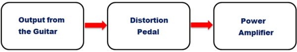
The distortion pedal produces a distorted sound on the musical notes. Generally, A Distortion pedal circuit is used in between the guitar audio source and the Power Amplifier. A simple block diagram of a guitar with a distortion circuit looks like this below.
Distortion pedals are made using a minimum of the two most important things, namely the preamplifier section and the diode clipping circuit. The Audio preamplifier section adds up the gain to the input signal and the diode clipping section clips or chops out the positive and negative peak of the audio signal. Often, distortion pedals are also called as overdrive or fuzz pedals.
Components Required
In this article, we are going to build a transistor-based Distortion circuit. The components that are required for constructing the basic distortion pedal circuit are –
- BC337-25 transistor
- .1 uF capacitor – 2pcs
- 100k resistor
- 1 meg resistor
- UF4007 – 2pcs
- 2 audio input sockets
- Breadboard
- Hooking wires
- 12v adapter (9V will also work)
Guitar Distortion Pedal Circuit Diagram
In the below image, a basic distortion pedal schematic using a transistor is shown. The transistor acts like a basic preamplifier. The 100K resistor is used as a collector resistor and the two capacitors are used for the audio input and audio output related purposes. The capacitors will block any DC and only pass the AC signal. The capacitor’s value can be selected from .1 microfarad to 10 microfarads.
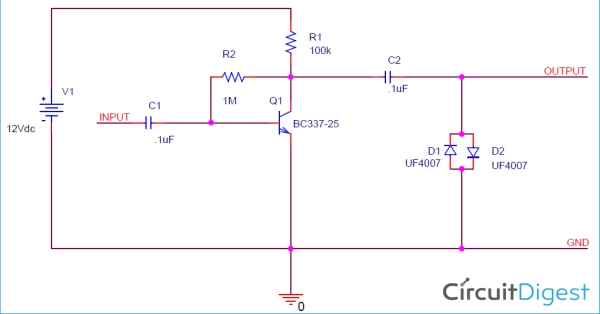
The selection of the transistor is essential for this project. In the above circuit, we used BC337-25 transistors. This transistor provides pretty good gain to the input signal. One can use other transistors as well.
Two diodes D1 and D2 create a diode clipping circuit. This is the place where the distorted sound is created. Let’s assume that the input signal is an AC sinusoidal signal that looks like the below image.
It is a perfect sinusoidal wave. Now a diode clipping circuit like the one that is used in the schematic, chops off or clips the sinusoidal wave as per the diodes forward voltage. The clipped sinusoidal wave will look like the below image –
The diode D1 will be reverse biased with respect to the output and clips the negative peak of the output signal. Similarly, the diode D2 will be forward-biased with respect to the output clip and clips the positive peak of the output signal. Therefore if we compare these input and output signal, it will look like the below image
But how will this affect in distorted sound? That is due to the speaker’s response to the sinusoidal wave. When the sinusoidal wave goes positive the speaker diaphragm moves forward, when it goes negative the speaker diaphragm moves backward. But the Forward and Backward movement of the speaker goes smoothly due to the proper sinusoidal wave response. Whenever the signal is clipped or chopped down the speaker diaphragm creates a thrashing sound and the output tone gets distorted.
How much distortion is needed depends on the diodes configurations. A different forward voltage or even different specifications of diodes in D1 and D2 produces different kinds of distorted sound.
Possible combinations include 1N4148 in D1 and Green LED in D2, or Orange and Green LED in D1 and D2, or Germanium diodes configurations also work. Different manufacturers of distortion pedals use different combinations in a single package and provide a selectable switch for the user. The user can choose which one to use as per the tonality. One can experiment with other diodes configuration and creates interesting distorted sound output.
Testing Guitar Distortion Circuit
The circuit that we explained above is constructed on a breadboard and tested with a real guitar. The breadboard set-up once the circuit was completed looks like this below.
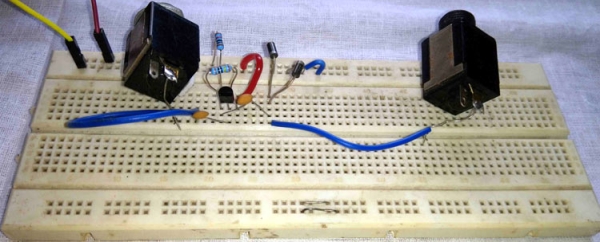
To test the circuit, I have used two patch cables, a Power Amplifier, and one guitar. The patch cables are connected to the two connectors (black colour) to get the audio input from the guitar and pass it on to the amplifier. However, the distortion pedal is generally used with electric guitar but since it is unavailable during the testing phase, an acoustic guitar is used here for our testing purposes.
The Power amplifier is a 5 Watt home-based amplifier system that I use for guitar practices. You use any amplifier of your choice, or build your own, we have previously built a lot of Audio Amplifier circuits ranging from small 10W amplifiers to heavy 100W Power amplifier.
Source: Build Your Own Guitar Distortion Pedal Circuit
- What is the primary function of a distortion pedal?
A distortion pedal produces a distorted sound by adding gain via a preamplifier section and clipping audio signal peaks using a diode clipping circuit. - How does the diode clipping circuit create distorted sound?
The diodes clip the positive and negative peaks of the sinusoidal wave, causing the speaker diaphragm to create a thrashing sound instead of smooth movement. - Can different types of diodes change the sound output?
Yes, different forward voltages or specifications such as 1N4148, Green LED, Orange LED, or Germanium diodes produce different kinds of distorted sounds. - What role do the capacitors play in the circuit?
The capacitors block any DC and only pass the AC signal for audio input and output purposes. - Which transistor is recommended for this specific circuit?
The BC337-25 transistor is used because it provides pretty good gain to the input signal, though other transistors can be used. - What components are needed to test the circuit?
Testing requires two patch cables, a power amplifier, and a guitar, though an acoustic guitar was used in this project due to unavailability of an electric one. - Is a 9V adapter suitable for powering this circuit?
Yes, a 9V adapter will work, although a 12V adapter is listed as the primary requirement. - Where is the distortion pedal placed in the audio chain?
The distortion pedal circuit is generally used between the guitar audio source and the Power Amplifier.