
Summary of Build a digital spirit level using a SCA610 accelerometer using PIC16F684
This article describes building a simple digital spirit level using a Microchip PIC16F684 microcontroller and a VTI SCA610 one-axis analog accelerometer. The SCA610 provides an analog voltage proportional to inclination; the PIC reads it via its 10-bit ADC, averages samples, drives five LEDs to indicate tilt direction, and sounds a buzzer until the board is perfectly horizontal. The PIC runs at 8 MHz internal oscillator; sensor output is on AN0, LEDs on RC0–RC4, buzzer on RC5. The design maps 1.25–3.75V to −90°…+90° inclination.
Parts used in the Digital Spirit Level:
- Microchip PIC16F684 microcontroller
- VTI SCA610 one-axis analog accelerometer
- Five LEDs (arranged in a row)
- Buzzer (ON/OFF type)
- Resistors (for LEDs and sensor pull-ups as required)
- Capacitors (for decoupling and oscillator stability as required)
- Power supply providing precise +5.0V
- PCB or prototyping board and wiring
- Optional connector or mounting hardware for accelerometer orientation
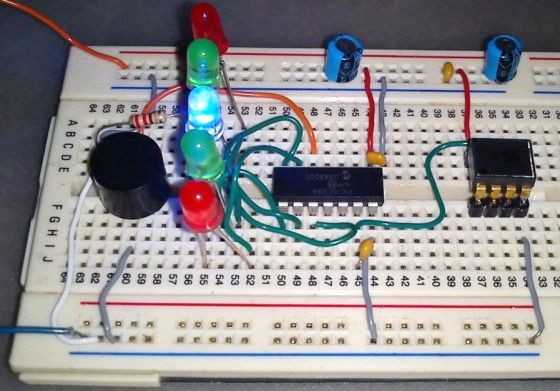
A bubble or spirit level meter, like the DIY Digital Spirit, is a handy tool to find whether a surface is horizontal or vertical. It is often carried by civil engineers, mechanical engineers, surveyors, carpenters, and many other professionals whose work involves precise alignments of horizontal and vertical planes.. Original spirit levels had two banana-shaped curved glass vials at each viewing point and were much more complicated to use. Mechanical spirit level meters are still available both in 1D and 2D formats. However at present time their electronic counterparts have also emerged and are even available in modern Android equipped cell phones. It’s from there I got my inspiration to make a very simple digital spirit level. Here’s a demo of such an electronic spirit level made by using a Microchip PIC16F684 micro, a SCA610 accelerometer and a handful of other discrete components.
Theory
The heart of this project is the SCA610 accelerometer IC that senses the inclination of a surface. Bases on VTI 3D MEMS technology, SCA610 is a very reliable, accurate and stable one-axis analog accelerometer. It requires a single power supply and provides an analog output voltage proportional to the inclination. According to its datasheet, if the device is powered with a precise +5.0V, the analog output voltages for +1g (vertical), 0g (horizontal), and -1g (vertical in opposite direction) inclinations would be 3.75V, 2.50V, and 1.25V, respectively. Voltages between 1.25V and 3.75V are linearly interpolated and mapped to the inclination angles varying from +90° to -90°. The analog signal can be processed by a microcontroller through an ADC channel to retrieve the inclination information.
Circuit diagram
The microcontroller used in this project is PIC16F684 which has just enough I/O pins and a built-in 10-bit A/D converter required for this project. The microcontroller runs at 8.0 MHz using the internal oscillator. The SCA610 sensor output goes to AN0 ADC channel of PIC16F684. The microcontroller takes quick multiple ADC samples which are averaged for a better estimation of inclination angle. There are five LEDs connected to RC0 through RC4 port pins and they are arranged in a row. Based on the direction of inclination the LEDs run in either forward or in reverse direction. There is a buzzer connected to RC5 pin which beeps continuously until the entire board settles at 0g or horizontal position. The buzzer used in the circuit is a ON/OFF type. What that means is it turns on when the RC5 pin goes high. If the device is aligned perfectly horizontal then only a central blue LED flashes and the buzzer mutes.
The axis direction of the SCA610 accelerometer is marked on the chip, as shown in the circuit diagram above.
For more detail: Build a digital spirit level using a SCA610 accelerometer using PIC16F684
- What sensor is used to sense inclination?
The SCA610 one-axis analog accelerometer is used to sense inclination. - Which microcontroller reads the accelerometer output?
The PIC16F684 microcontroller reads the accelerometer output via its ADC. - How is the accelerometer output connected to the PIC?
The SCA610 analog output is connected to the AN0 ADC channel of the PIC16F684. - How does the circuit indicate which way it is tilted?
Five LEDs connected to RC0 through RC4 run forward or reverse according to tilt direction. - What does the buzzer do?
The ON/OFF buzzer on RC5 beeps continuously until the board settles to 0g horizontal; it mutes when perfectly horizontal. - How are ADC readings improved for accuracy?
The microcontroller takes multiple quick ADC samples and averages them for a better inclination estimate. - What voltage corresponds to 0g (horizontal) on the SCA610?
The SCA610 outputs 2.50V for 0g horizontal when powered at +5.0V. - What output voltages correspond to +1g and −1g?
With +5.0V supply, the SCA610 outputs about 3.75V for +1g and 1.25V for −1g.
