Summary of Breakout board for 18-pin PIC16F series microcontrollers
This article describes the design and assembly of a breakout board for 18-pin PIC16F series microcontrollers, such as the PIC16F628A and PIC16F1827. The board includes essential components like tact switches for reset and user input, LEDs for power indication and user output, and a 3-pin ceramic resonator for clocking. It offers accessible headers for easy experimentation with PORTA and PORTB pins and supports in-circuit serial programming via a 5-pin ICSP header, facilitating quick testing and development.
Parts used in the Breakout board for 18-pin PIC16F series microcontrollers:
- 18-pin PIC16F microcontroller (e.g., PIC16F628A or PIC16F1827)
- Two tact switches (one reset, one user input)
- Two LEDs (power-on indicator and user output)
- 2-pin DIP switch (connecting user input switch and output LED to RB0 and RB1)
- 3-pin ceramic resonator with built-in load capacitors
- Header pins for PORTA and PORTB accessibility (male, female, or right-angled)
- 5-pin ICSP header for programming (compatible with PICkit2 or PICkit3)
The 18-pin microcontrollers from PIC16F series have always been my favorite processors. They are small in size (so occupies less area on the circuit board), and are very easy to use. Besides they are capable enough to do most projects that don’t require a large amount of computational capability. I have used PIC16F628A and PIC16F1827 in most of my tutorials and projects posted on http://www.Embedded-Lab.com.
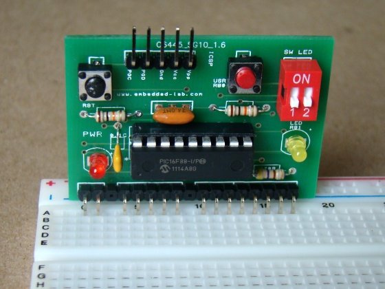
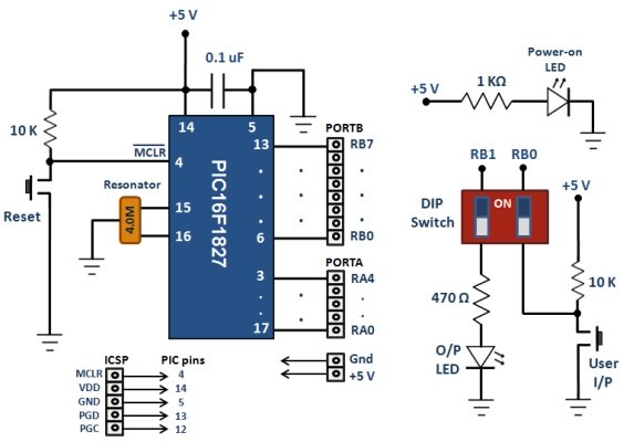
 I have found them very handy and will be using them more in the future. So I thought of making of a breakout board for 18-pin PIC16F series. I recently used iTeadStudio’s inexpensive PCB service for making PCBs of the board. Here are some pictures that show the circuit diagram and the assembled board.
There are two tact switches on the board: one for reset and other for user input. Similarly, there are two LEDs: one for power-on indicator and the other for user output. The input tact switch and the output LED can be connected to RB0 and RB1 pins respectively through a 2-pin dip switch.
 The switch and the LED are useful for a quick test of the board. The microcontroller clock is derived using an external ceramic resonator having 3 pins with built-in load capacitors. PORTA (RA0-RA4) and PORTB (RB0-RB7) pins of the microcontroller are accessible for experimenting through header pins (male, female, or right-angled). A 5-pin header is also available for ICSP programming through a PICkit2 or PICkit3.
For more detail: Breakout board for 18-pin PIC16F series microcontrollers
