
Summary of BATTERY CHARGE CIRCUIT 12V 12AH
This article describes a 12V 12AH lead-acid battery charging circuit controlled by a PIC16F876 microcontroller. The system utilizes an adjustable L200 regulator IC to manage voltage and current, while LEDs indicate battery levels and control start/stop functions. The project includes source code written in Mikropascal and simulation files created with Proteus ARES PCB and ISIS software.
Parts used in the Lead Acid 12V 12AH Battery Charging Circuit:
- PIC16F876 microcontroller
- 12V 12AH Lead Acid battery
- L200 regulator IC
- LEDs for status indication
- Mikropascal source code
- Proteus ARES PCB design files
- Proteus ISIS simulation files
Lead Acid 12V 12AH battery charging circuit PIC16F876 microcontroller based on the 16f876 LEDs and battery level show and start, stop doing their work forces in the sight of the voltage, current, adjustable L200...Electronics Projects, Battery Charge Circuit 12V 12AH “battery charger circuit, microchip projects, microcontroller projects, pic16f876 projects, “

Lead Acid 12V 12AH battery charging circuit PIC16F876 microcontroller based on the 16f876 LEDs and battery level show and start, stop doing their work forces in the sight of the voltage, current, adjustable L200 regulator IC is used 12V 12AH battery charging circuit’s source mikropascal codes and Proteus ARES pcb, isis simulation There are files
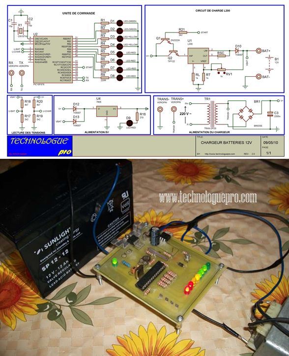
source: BATTERY CHARGE CIRCUIT 12V 12AHalternative link: battery-charge-circuit-12v-12ah.rar alternative link2
- What microcontroller is used in this battery charging circuit?
The project uses a PIC16F876 microcontroller. - How does the circuit control the charging process?
It uses LEDs and battery level indicators to show when to start or stop based on voltage and current. - Which regulator IC is used for voltage and current adjustment?
An adjustable L200 regulator IC is used in the circuit. - In what programming language is the source code written?
The source code is written using Mikropascal. - What software tools were used for simulation and PCB design?
Proteus ARES was used for PCB design and Proteus ISIS for simulation. - What type of battery is this circuit designed to charge?
The circuit is designed specifically for a 12V 12AH lead-acid battery. - Can the voltage and current be adjusted in this circuit?
Yes, the circuit uses an adjustable L200 regulator IC to manage voltage and current.
