Summary of Basic Servo Motor Controlling with Microchip PIC Microcontroller
Summary: This tutorial explains controlling hobby servo motors using a PIC16F690 microcontroller. It covers servo types (standard vs continuous), PWM-based position control (around 50 Hz, 20 ms period), typical pulse widths for CW, center, and CCW, wiring (signal, Vcc, Gnd), and notes using the PIC PWM peripheral and TIMER2 prescaler limitations when running an 8 MHz internal clock.
Parts used in the Basic Servo Motor Controlling with Microchip PIC Microcontroller:
- Servo motor (Parallax Continuous Servo in tutorial)
- PIC16F690 microcontroller
- Power supply (Vcc and Gnd for servo)
- Connecting wires (White signal, Red Vcc, Black Gnd)
- Microcontroller development hardware or breadboard
The servo motor is widely used in model hobbyist such as airplane R/C model for moving the rudder, ailerons, elevators and acceleration control or in the car R/C model for steering and acceleration control. In this tutorial we will learn how to control the servo motor as well as the simple close loop control algorithm for this servo motor.
The servo motor basically is a high quality geared DC motor equipped with electronic circuit for controlling the DC motor rotation direction and position. Currently there are two types of servo motor available on the market, the first one is called standard servo and the other one is called continues servo; standard servo can rotate to maximum (clockwise or counterclockwise) of 120 to 180 degrees while continues servo can rotate up to 360 degrees in both direction.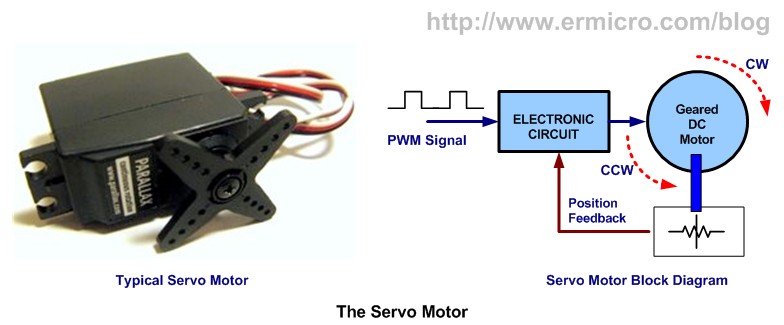
The Servo Motor
The servo motor use PWM signal for controlling the DC motor; unlike normal PWM usually used in ordinary DC motor; this PWM signal is not use for controlling the rotation speed, instead it is use for controlling the motor direction or position. Most servo motor will work well on 50 Hz of PWM frequency; this mean the PWM signal should have a period of 20ms. The electronic circuit inside the servo motor will response to the PWM signal width; the 0.7ms to 1ms PWM width will make the servo motor to turn clockwise (CW), the 1.7ms to 2ms PWM width will make the servo motor to turn counterclockwise (CCW). For the standard servo the 1.5ms PWM width will turn the servo motor to its center.
The exact PWM width is depend on the servo motor types and brands; on this tutorial we will use the Parallax Continues Servo which using 1ms and 2ms respectively. The Parallax servo motor consists of three wires colored with White, Red and Black. The Red and Black wires go to the Vcc and Gnd, while the White wire is use to feed the PWM signal from the PIC 16F690 microcontroller I/O port.
Driving the servo motor using PIC 16F690 microcontroller might be simple as you thing at the first time; we just use the PIC PWM peripheral to do the job (you could learn of how to use the PIC PWM peripheral on the article H-Bridge Microchip PIC Microcontroller PWM Motor Controller posted on this blog), but looking at the PIC 16F690 datasheet with the 8 Mhz of internal frequency clock (use in this tutorial) and using maximum prescaler of 16 (TIMER2) the minimum PWM frequency we could achieve can be calculated using this formula:
For more detail: Basic Servo Motor Controlling with Microchip PIC Microcontroller
- What types of servo motors are described in the article?
The article describes standard servos (120–180 degrees) and continuous servos (up to 360 degrees). - How is servo position controlled?
Servo position is controlled by PWM pulse width, typically at 50 Hz (20 ms period), where different pulse widths set direction or center. - What PWM pulse widths correspond to clockwise, center, and counterclockwise?
Approximately 0.7–1 ms for clockwise, 1.5 ms for center, and 1.7–2 ms for counterclockwise; Parallax continuous servo uses about 1 ms and 2 ms. - Which wires are used on the Parallax continuous servo and their functions?
Red is Vcc, Black is Gnd, and White is the PWM signal input from the PIC16F690. - What microcontroller peripheral is used to drive the servo?
The PIC PWM peripheral is used to generate the required PWM signal. - What clock and timer settings are referenced in the tutorial?
The tutorial uses the PIC16F690 with an 8 MHz internal clock and mentions TIMER2 with a maximum prescaler of 16 affecting achievable PWM frequency. - Is the servo PWM used to control speed as in ordinary DC motors?
No, the servo PWM is used to control motor direction or position, not rotation speed.