Summary of BA1404 HI-FI Stereo FM Transmitter 88 – 108 MHz usnig pic microcontoller
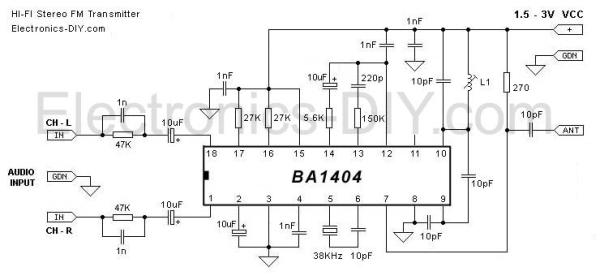
This BA1404 HI-FI Stereo FM Transmitter transmits stereo audio (88–108 MHz) from devices like iPods using a BA1404 IC, 38 kHz crystal encoder, and a tunable 3.5-turn RF coil for frequency stability and range. Designed for low-voltage operation (1.5–3V), it emphasizes sound quality via decoupling capacitors, a PCB ground plane, and a crystal-stable stereo encoder. Antenna length recommendations for quarter-wave or half-wave operation are provided.
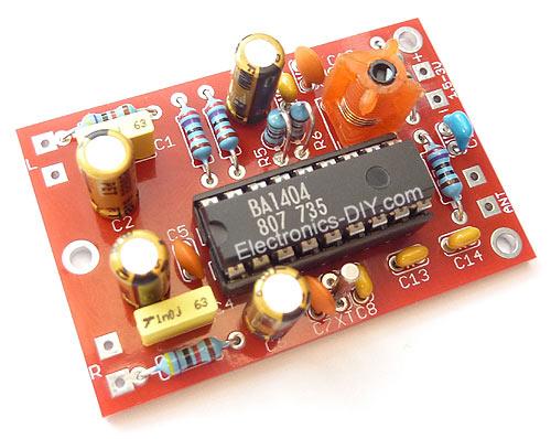
Parts used in the BA1404 HI-FI Stereo FM Transmitter:
- BA1404 IC
- 38KHz Crystal
- L1 - 3.5 Turns Variable Coil (3.5T Variable Precision RF Coil)
- 1x PCB
- 1x 38KHz Crystal Oscillator
- 1x DIP-18 IC Socket
- 1x 10uH Inductor
- 4x 10uF/50V Gold Audio Capacitors
- 4x 1nF Ceramic Capacitors
- 2x 1nF Mylar Capacitors
- 1x 220pF Ceramic Capacitor
- 5x 10pF Ceramic Capacitors
- 2x 47K 1% Metal Film Resistors
- 2x 27K 1% Metal Film Resistors
- 1x 150K 1% Metal Film Resistor
- 1x 5.6K 1% Metal Film Resistor
- 1x 270 1% Metal Film Resistor
|
|
Another quality of the presented BA1404 transmitter is a crystal clear stereo sound and improved sound separation. There are several factors that account for improved sound quality and a separation. First reason is the use of 38 KHz crystal which provides rock solid frequency for stereo encoder. Another reason is the use of two 1nF decoupling capacitors one for BA1404 chip and another for 3.5 variable coil. These capacitors have to be as close as possible to a BA1404 chip and a variable coil because this will GREATLY improve the sound quality, sound separation and even frequency stability as well. What they do is filter out the noise in the incoming DC voltage. If the noise enters BA1404 chip stereo generator will include it in a transmitted sound affecting both the sound and multiplex signal that is responsible for generation of the clear stereo signal. If that noise enters it will also be included in a generation of subcarrier frequency affecting the frequency stability. Most people are not aware of how important this is and might place them in a wrong location, away from the target components which provides no use, or worse decide not to use these capacitors at all.Another factor that is extremely important and which improves overall quality of the whole BA1404 transmitter including frequency stability, sound quality and sound separation is the use of the ground plane on the transmitter’s PCB. It is recommended that ground plane should always be used in circuits that deal with higher frequencies.
 Antenna
For optimum transmission range the length of the antenna should be 1/4 or 1/2 of the wave length of the transmitted frequency. Use this simplified formula to determine the antenna length for 1/4 wave length antenna type:
(30000 / Transmitted Frequency) / 4 = Antenna Length (in cm)
Example:
(30000 / 88MHz) / 4 = 85cm Antenna
(30000 / 108MHz) / 4 = 70cm Antenna
- What supply voltage does the transmitter use?
The transmitter operates from 1.5 to 3V according to the article. - What provides frequency stability for the stereo encoder?
A 38 kHz crystal is used to provide a rock solid frequency for the stereo encoder. - Why is a 3.5 turn variable coil used instead of an air coil?
The 3.5 turn variable coil minimizes frequency drift because its wire is partially embedded in plastic, making it more temperature stable than an air coil. - How do decoupling capacitors affect sound quality?
Two 1nF decoupling capacitors placed close to the BA1404 chip and variable coil filter DC noise, improving sound quality, separation, and frequency stability. - Is a ground plane recommended for this transmitter?
Yes, the article recommends using a ground plane on the PCB to improve frequency stability and overall quality. - How long should the antenna be for optimal range?
For a quarter-wave antenna use the formula (30000 / Transmitted Frequency) / 4 to get antenna length in cm. - Can the transmitter run from a single battery cell?
Yes, it can work from a single 1.5V cell and also from two 1.5V cells for maximum range. - What audio sources can be used with this transmitter?
The transmitter can send audio from iPod, computer, discman, walkman, TV/SAT receiver, and many other audio sources.