Summary of A PIC Ultrasonic distance meter project using a Seven Segment display and a PIC micro.
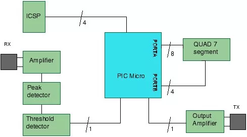
The article describes a PIC-based ultrasonic distance meter that transmits 40 kHz pulses and measures echo return time with a PIC microcontroller (16F88) using the CCP capture module and a 4 MHz internal oscillator. It uses a three-transistor receiver amplifier, peak detector and comparator for echo detection, and transistors to drive the transmitter. Range is about 5 cm to ~200–300 cm with ±3 cm accuracy; speed of sound (340 m/s by default) is used in distance calculation. Project files (C source and hex) are available for download and the design is educational and retargetable.
Parts used in the PIC Ultrasonic Distance Meter:
- PIC microcontroller (target 16F88)
- Ultrasonic transducer pair (40kHz TX and RX)
- Five standard transistors (used for transmit and receive stages)
- Three-transistor high-gain receiver amplifier
- Peak detector circuit
- Comparator (external comparator for threshold detection)
- Timer/capture hardware (CCP module on PIC)
- 4MHz internal oscillator (PIC configured to use internal clock)
- Multiplexed display (driven by the PIC)
- Support passive components (resistors, capacitors)
- Power supply components (regulator, decoupling capacitors)
The PIC Ultrasonic distance meter works by transmitting a short pulse of sound at a frequency inaudible to the ear (ultrasonic sound or ultrasound).
Afterwards the microcontroller listens for an echo.
The time from transmission to echo reception lets you calculate the distance from the object.
PIC Ultrasonic Distance Meter Specification
| Range | ~5cm – 300cm (approx.) |
| Accuracy | +/-3cm |
| Transducer frequency | 40kHz |
| Internal oscillator frequency | 4MHz |
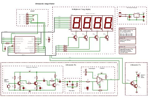
The project uses 5 standard transistors to receive and transmit the ultrasound and a comparator to set the threshold echo detection level – so there are no special components other than the microcontroller and the ultrasonic TX/RX modules which are standard 40kHz types.
Note: As you approach 300cm it is more difficult to receive a reflected signal so the practical range is probably nearer 200cm. The SR04 unit will perform better since it uses higher gain opamps.
Design
This design is experimental and educational since you can buy ready made modules such as the SR04 which are undoubtedly convenient – you supply a pulse trigger and they provide a distance (pulse width coded). These are quick and very easy to use but do not demonstrate what is going on.
This design uses external components, comparators and transistors to achieve the same result.
The 16F88 also has a built in comparator and reference level generator which would save components but this design can be used with any microcontroller that has a capture module. It is probably possible to use it with a 16F84 using some careful coding for time measurement.
Specification
Note that the internal oscillator of the PIC micro is used and this saves two pins – that can be used as normal I/O pins.
| Compiler | Mikroelectronika MikroC compiler Free! |
| Target | 16F88 (retargetable to other PICs that have a CCP module). |
| Software level | Medium. |
| Software notes | Drives multiplexed display, controls CCP, interrupt use. |
| Hardware level | Medium. |
| Hardware notes | High gain transistor amp. |
| Project version | 1.03 |
| Project files | Enter your details to get the Download Link and get the microcontroller newsletter: (Your email is safe it will never be sold or rented). Note: Check your email for the project code download link. |
You can recompile the project files if you want examine code operation (using the built in simulator) or change the source code. Note the hex file is contained in the download so you do not have the recompile the source code.
How the PIC Ultrasonic Distance Meter works
The time from transmission of the pulse to reception of the echo is the time taken for the sound energy to travel through the air to the object and back again.
Since the speed of sound is constant through air measuring the echo reflection time lets you calculate the distance to the object using the DST equation :
Distance = (s * t)/2 (in metres)
You need to divide by 2 as the distance is the round trip distance i.e. from transmitter to object and back again.
Where:
| s [m/s] | the speed of sound in air |
| t [s] | the round trip echo time. |
Some delay times:
| Round trip echo time | Distance |
| t = 588us | 10cm |
| t = 5.8ms | 1m |
Note: The speed of sound in air is more or less constant at 330m/s (@ 0ºC) – it varies mainly with temperature (~340m/s @ 20ºC). In this project I am using a value of 340m/s i.e. it is assumed that the project is used indoors. You can change it to whatever you like by modifying the code.
You can get ultrasonic transducers optimized for 25kHz, 32kHz, 40kHz or wide bandwidth transducers. This project uses a 40kHz transducer but it will still work with the others if you make simple changes to the software. The receiver and generator circuits will work as they are.
Note: If you use a different transducer you must change the software to generate the correct frequency for the transducer as they only work at their specific operating frequency.
The 40kz signal is easily generated by the microcontroller but detection requires a sensitive amplifier. I have used a three transistor amplifier for the receiver.
This is followed by a peak detector and comparator which sets the sensitivity threshold so that false reflections (weaker signals) are ignored.
CCP – Capture mode
This project makes use of the CCP module (in its capture mode) to accurately measure the signal reception time at the CCP port pin. When a signal triggers the CCP module the value of timer 1 is stored in a CCP register (or captured).
If you store the value of timer 1 and then enable the CCP after transmitting an ultrasound pulse the CCP will trigger when the comparator activates i.e. as soon as an ultrasonic echo is received.
Subtracting the stored value from the CCP register value gives the time delay in machine cycles. Since the project uses a 4MHz main clock then the time delay will be measured in micro-seconds.
PIC Ultrasonic Distance Meter Practical limits
The minimum distance of this scheme is about 5cm. Looking at the output of the first receiver amplifier shows a that it should be more accurate at lower distances – it is inaccurate by about 2cm which is still quite good. Probably the addition of amplifiers for the longer range stops accurate short range operation.
The maximum distance is limited by the sensitivity, gain and noise performance of the receive amplifier and also the transmit power and duration of transmission.
For this circuit the maximum distance is about 3m.
For more detail: A PIC Ultrasonic distance meter project using a Seven Segment display and a PIC micro.
- What frequency transducers does the project use?
The project uses standard 40kHz ultrasonic transducers. - What microcontroller is targeted by the project?
The project targets the PIC16F88 but can be retargeted to other PICs with a CCP module. - How is distance calculated in the project?
Distance is calculated using Distance = (s * t)/2 where s is the speed of sound and t is the round trip echo time. - What is the practical range of the device?
The stated range is approximately 5cm to 300cm, with practical reliable range nearer 200cm for this circuit. - What accuracy does the project achieve?
The project specification lists an accuracy of plus or minus 3cm. - How does the PIC measure the echo time?
The PIC uses the CCP module in capture mode to store Timer1 when the comparator output indicates an echo, and the difference gives the echo time. - What amplifier is used for the receiver?
A high-gain three-transistor amplifier is used followed by a peak detector and comparator for sensitivity control. - Can the project use other transducer frequencies?
Yes, it can work with other frequencies but the software must be changed to generate the correct transmit frequency. - Does the project use the PIC internal oscillator?
Yes, the internal 4MHz oscillator is used to save pins for I/O. - Are project source files provided?
Yes, C source code and the hex file are provided in the project download after entering details.